¶ BMCU Assembling
⚠️WARNING
Do not hot-plug or unplug the connection cable between the BMCU and the printer while the printer is powered on. -> Risk of damage to the BMCU motherboard
You may receive a different version of the BMCU motherboard, or download a different version of the stl model, please check before printing and assembling
¶ Version & author
- v1.1&v1.31
- 130 Improved shell version
- Editor: 山竹
¶ Step 1: Testing the PCB Hardware
-
Ensure Successful Firmware Burning for the BMCU Main Board (Firmware V0.2)
- Use a USB-to-TTL burner to power the main board. The red indicator light should turn on.
- Connect the printer using an MX3.0 4-pin cable. The main board's blue indicator light should turn on.
-
Verify the Functionality of the Secondary Board
- Power the secondary board via USB. When connected to the main board:
- RGB Lights:
- The RGB light on the secondary board should show blue (port 1 is blue, ports 2, 3, 4 are off).
- The light flashing is considered normal.
- Photoelectric Indicators:
- The two photoelectric indicator lights should remain off under normal conditions.
- When the photoelectric sensors detect obstruction, the corresponding rear indicator light should turn on.
- For material detection:
- RGB Light Behavior:
- When feeding, the RGB light should turn blue.
- When a material jam occurs, the RGB light should turn red.
- RGB Light Behavior:
- When powered by a
Bambulabprinter:- The RGB lights on both the main and secondary boards should remain blue.
- The two photoelectric indicator lights should remain off unless obstruction is detected, in which case the corresponding rear indicator lights should turn on.
- The RGB lights should consistently remain blue.
- RGB Lights:
- Power the secondary board via USB. When connected to the main board:
-
Ensure Proper Communication Between the Main Board, Secondary Board, and Printer
- When the main board is connected to the printer, the printer's consumable menu should display the AMS option.
- When the photoelectric sensors are obstructed, the consumable status should update to reflect the material detected.
¶ Step 2: Mechanical Assembly part 1 - Feeder/extruder, needs to be repeated 4 times
-
Print the Complete Feeder Housing Set
- Print the feeder housing according to the provided model.
- This tutorial is based on the following model:
https://makerworld.com.cn/models/741793 (Modified by 青铜板子cn).
-
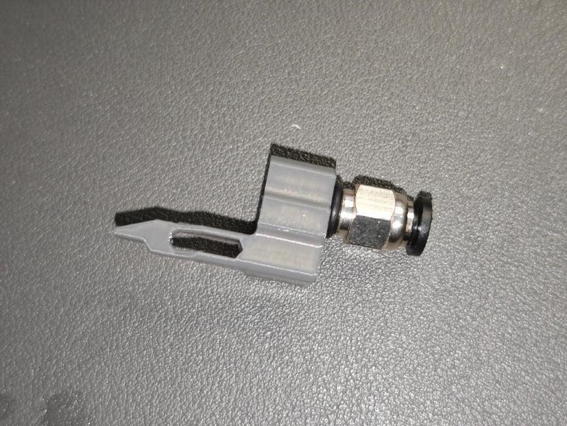
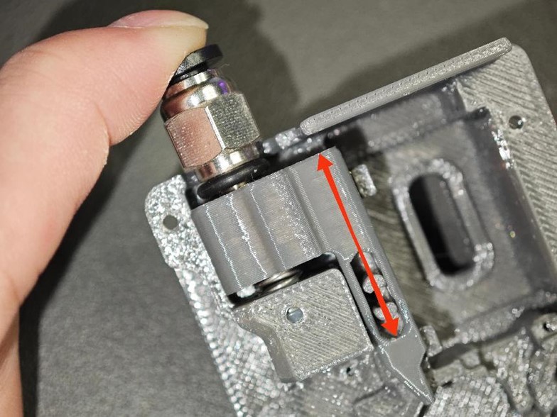
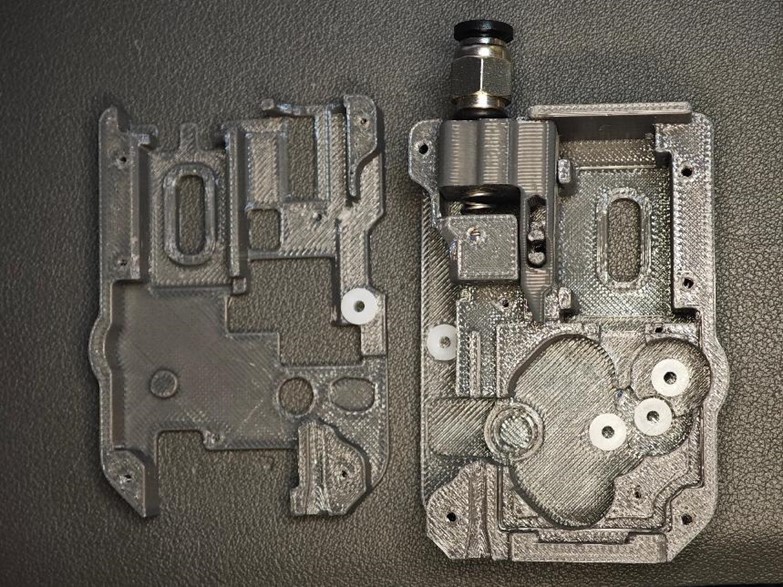
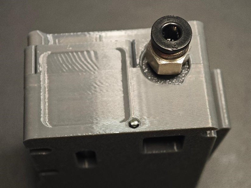
Attach the Pneumatic Fitting (PC4-M6)
- Screw the PC4-M6 pneumatic fitting into the buffer assembly.
- Caution: Ensure it is screwed in straight to avoid misalignment.
-
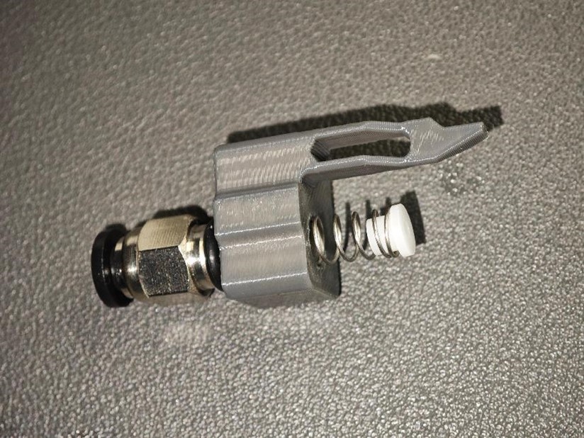
Assemble the Spring and the 62B Axle Sleeve
- Take one large spring (0.5 × 6 × 10mm) and a 62B axle sleeve.
- Assemble them as shown in the diagram below:
-
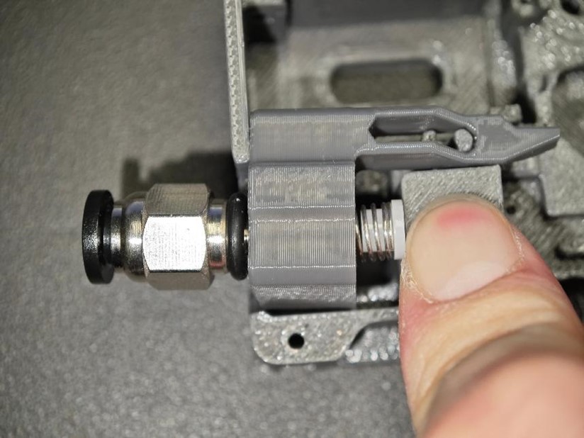
Compress the Spring and Snap it into the Base Housing
-
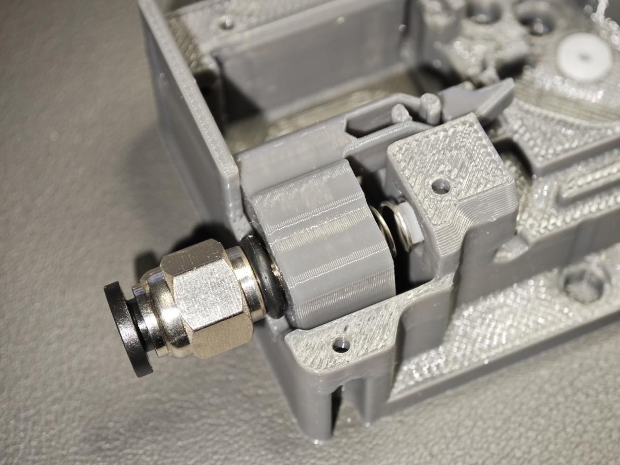
Ensure the Components Move Freely
-
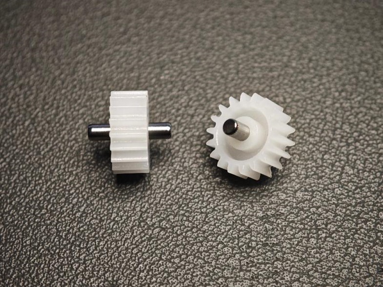
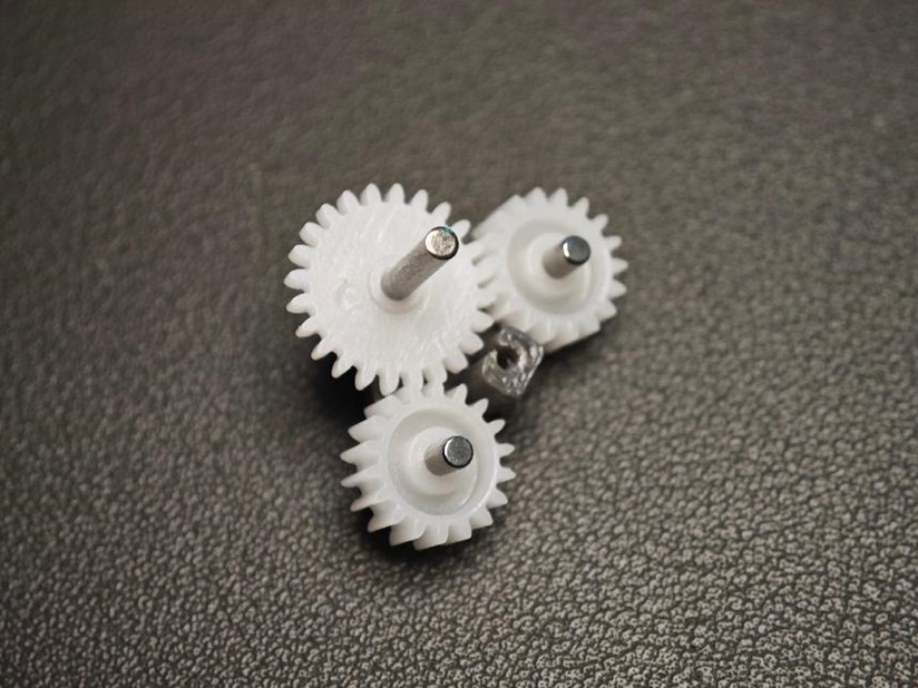
Assemble the Gear Structure
- Take two small gears (Gear 182A) and one short axle (2 × 10mm).
- Assemble them as shown in the diagram.
- Ensure the protruding sections on both sides of the axle are of equal length for proper alignment.
-
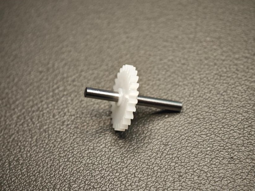
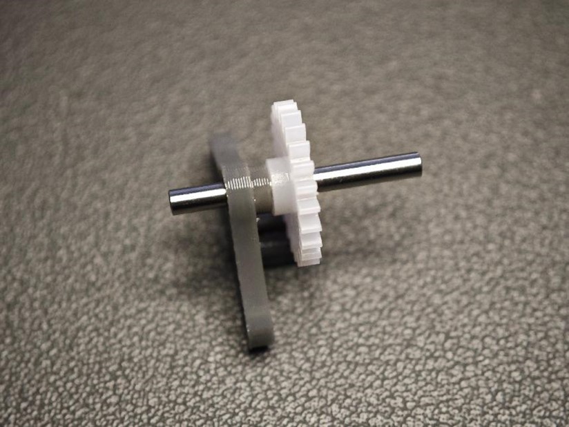
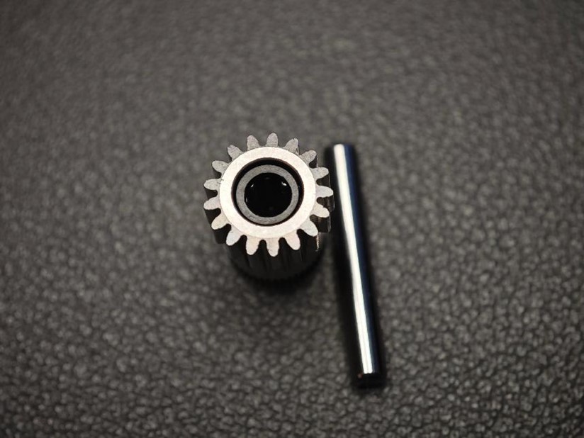
Assemble the Large Gear and Long Axle
- Take a large gear (Gear 242A) and a long axle (2 × 20mm).
- Assemble them to match the diagram, ensuring one end of the axle is pressed to the width indicated by the arrow in the diagram.
-
Select Two Triangular Parts (Replaceable)
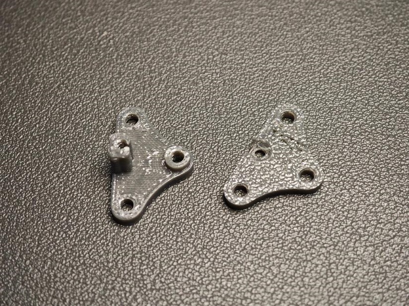
-
Assemble the Large Gear with the Triangular Parts
- Attach the large gear to the triangular parts as shown in the diagram.
- Important: Pay close attention to the orientation of the gear to ensure correct assembly.
-
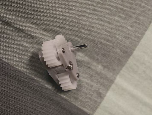
Assemble the Remaining Small Gears and Secure the Components
- Attach the remaining two small gears to the structure.
- Place the cover over the assembly and tighten it using M2 × 8 self-tapping screws.
- Ensure all screws are securely fastened to maintain stability.
-
Insert Axle Sleeves
- Insert 5 white 62B axle sleeves into the positions shown in the diagram.
- Ensure they are securely pressed into the base and top covers.
- Prepare BMG Extrusion Components
A word of caution: please handle the combination of BMG gear set, D5*2 shaft and bearings with care, as the fit of the gears and shafts is sometimes very tight, and if it unfortunately gets stuck, it is very difficult to get it out again
- Gather the following parts:
- Extrusion wheel with screw hole !!!!!! IMPORTANT
- Black set screw
- One thick axle (5 × 22mm)
- Two bearings (MR85ZZ).
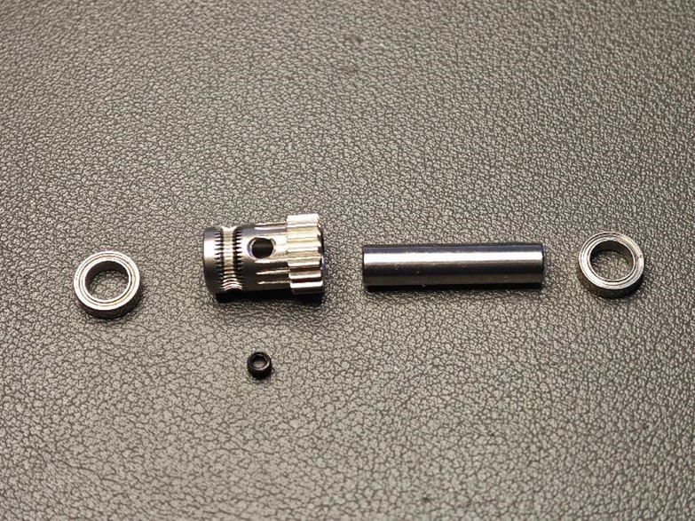
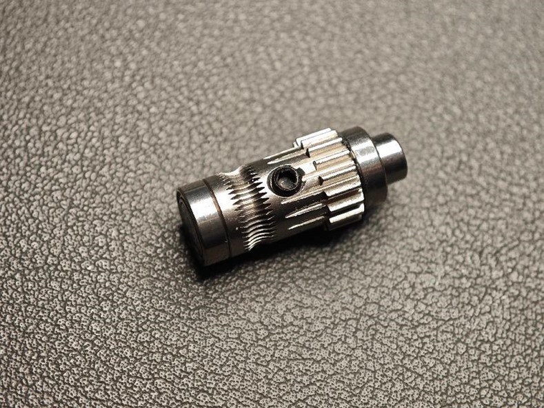
- Assemble the Extrusion Wheel
- Assemble as shown in the diagram, paying close attention to orientation.
- One end of the thick axle must be flush with the bearing (to allow a flat surface for the magnet).
- Don’t forget to install the black set screw.
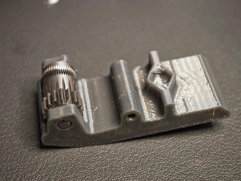
- Place the Extrusion Structure
- Insert the extrusion structure into the base housing.
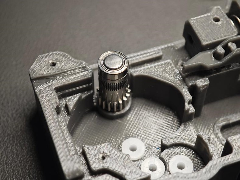
- Insert the Gear Group
- Place the gear group into the axle sleeves, ensuring the screw side faces downward, as shown in the diagram.
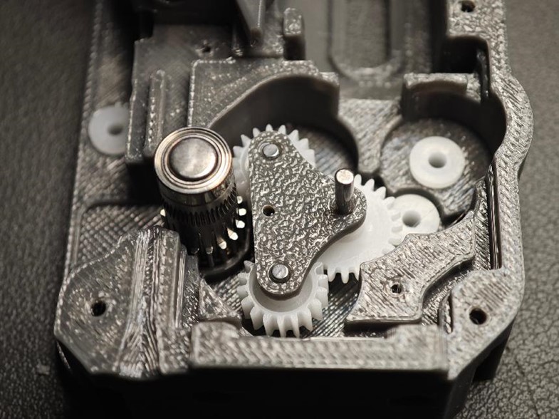
- Install Two Long Axles
- Prepare two long axles (2 × 20mm).
- Insert them into the 62B axle sleeves.
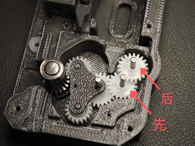
- Install two 20082B double-layer straight gears, starting from left to right.
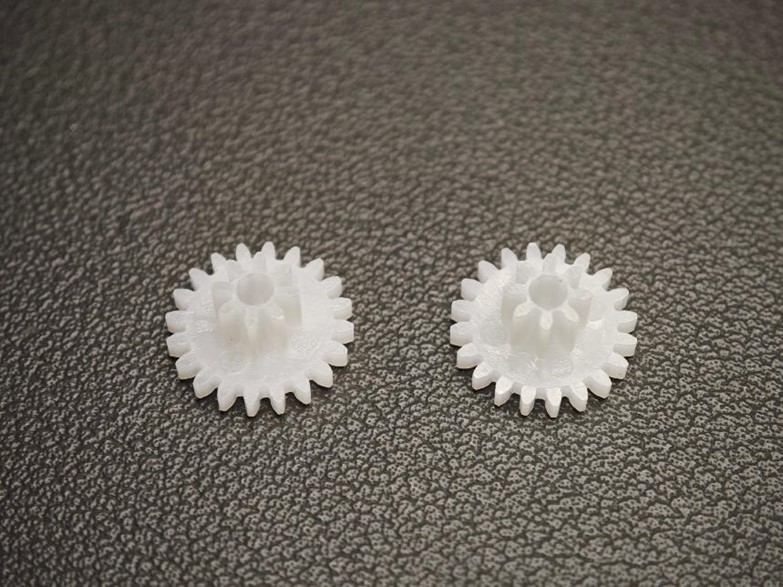
Note in image :
The left-down arrow gear is placed first,
The right-up arrow gear is installed later
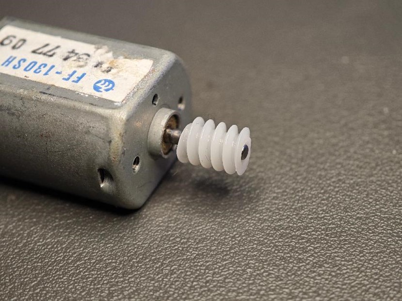
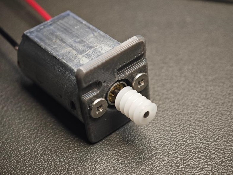
- Assemble the Motor and Worm Gear
- Combine the FF-130 motor with the 682A worm gear.
- Ensure the assembly is flush; misalignment can cause gear jamming.
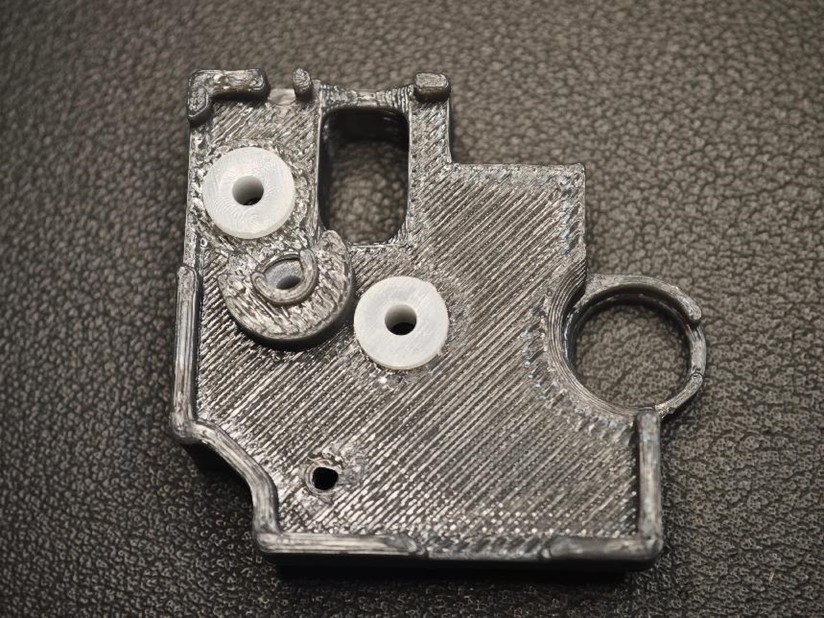
- Insert Axle Sleeves into Cover Plate
- Snap the 62B axle sleeves (white parts) into the holes on the cover plate, as shown in the diagram.
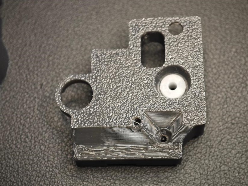
- Attach Motor Cover Plate
- Fix the motor cover plate with two M2 × 4 flat-head screws.
- Solder Motor Wires
- Solder the connection wires to the motor.
- Red dot indicates the positive terminal.
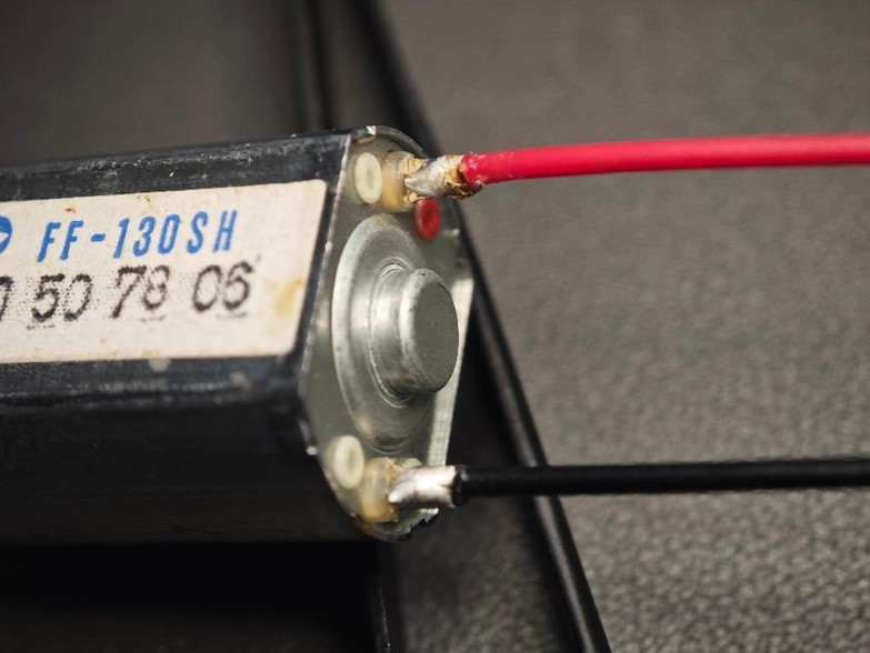
- Red dot indicates the positive terminal.
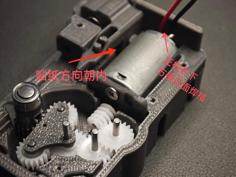
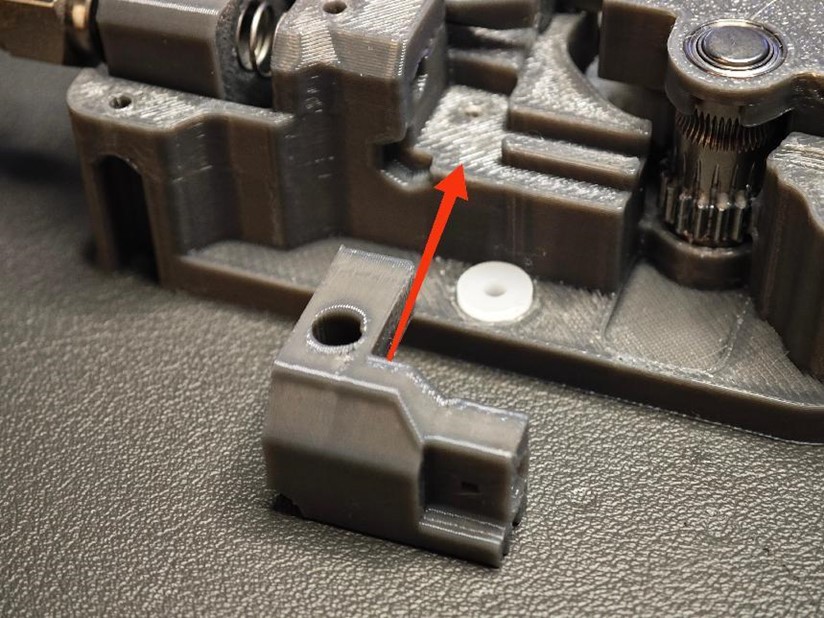
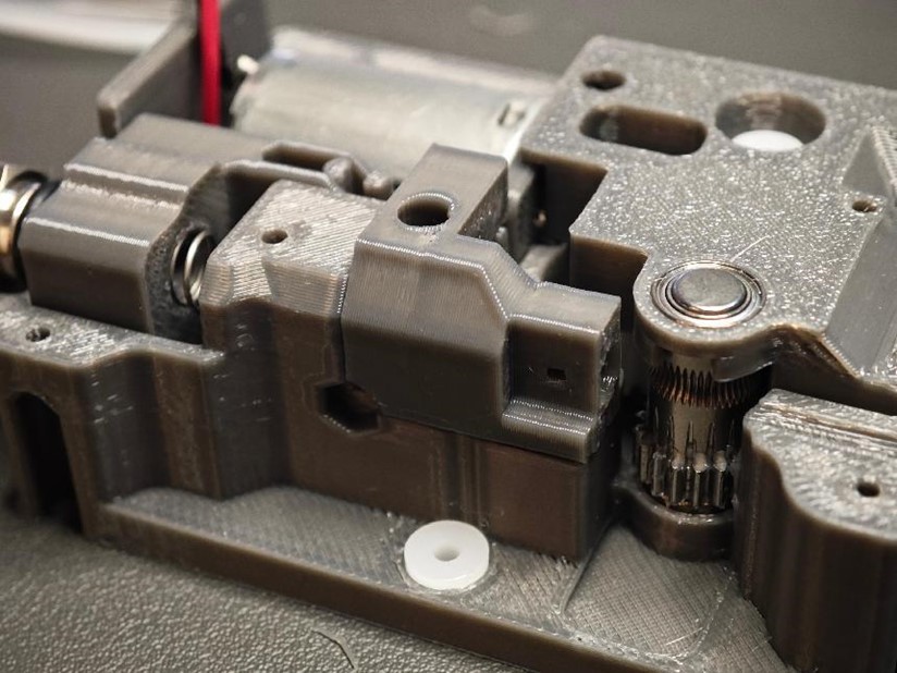
- Install and Test the Motor
- Place the motor into the base housing and align it with the fixing slot.
- Power the motor with 3V-12V to test if all gears rotate smoothly.
Note in image :
Motor with sticker side down.
The positive terminal should face downward for easier soldering later.
- Apply Lubricant and Secure the Cover
- Apply lubricating grease to the gears if desired.
- Place the cover plate on top and secure it with M2 × 8 screws.
- Insert the Replaceable Optical Sensing Module
- Place the optical sensing module into its designated slot.
- Thread Motor Wires Through Top Cover
- Thread the motor wires through the slots on the top cover and secure the cover in place.
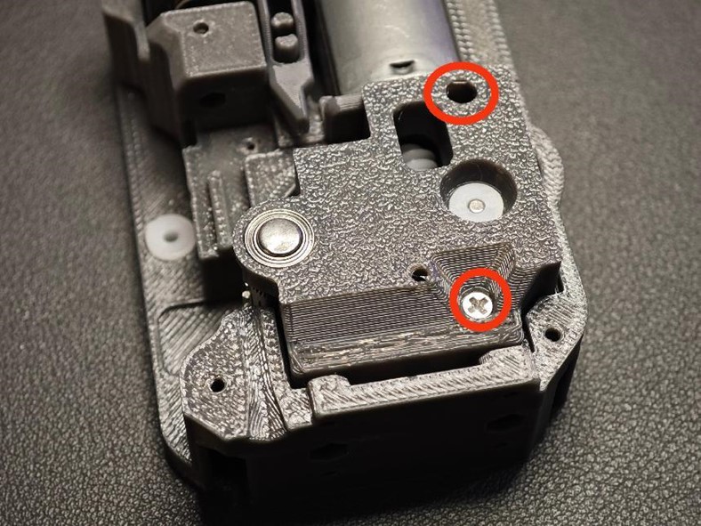
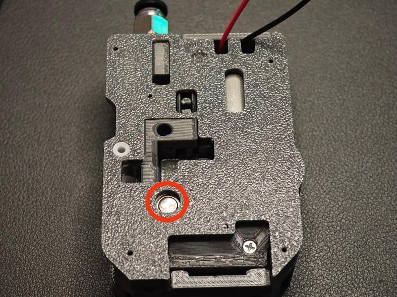
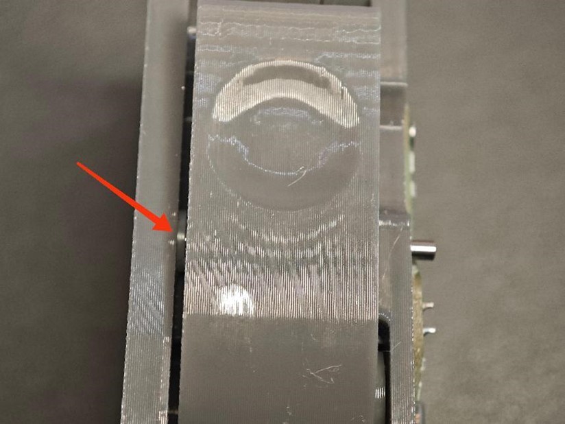
- Insert Radial Magnet
- Insert a radial magnet (6 × 2.5mm) into the red-circled hole on the top cover.
- Important: Ensure smooth rotation and use the correct magnet size (not replaceable by a standard magnet).
Note: This magnet is used to detect the angle of rotation of the extrusion gear to obtain the material feed length.
- Secure the Back Cover Screws
- Tighten the five screws (M2 × 8 self-tapping screws) on the back cover, as shown in the diagram.
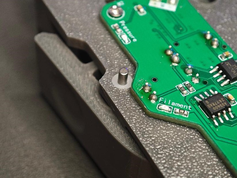
- Install the Secondary Board
- Insert the secondary board and solder the motor wires (observe polarity).
- Secure the secondary board with two M2 × 8 self-tapping screws.
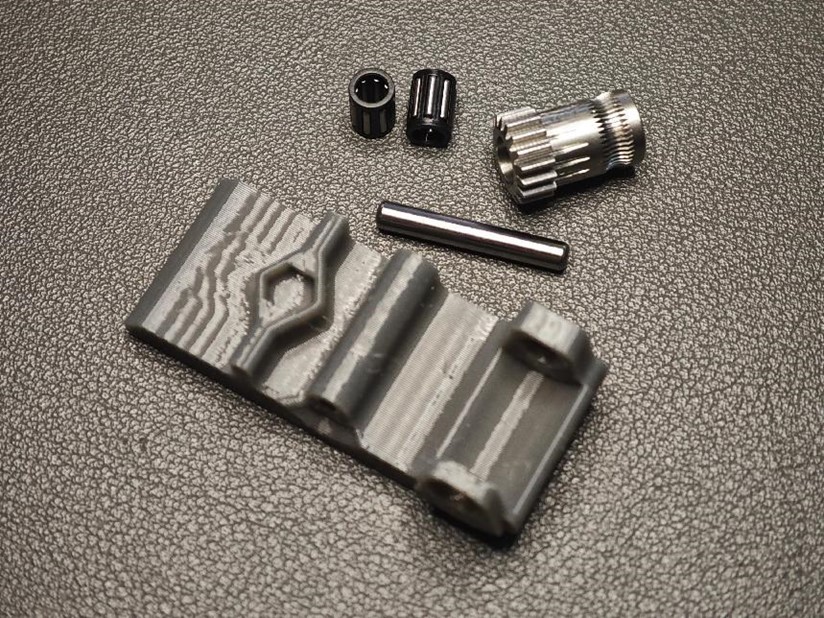
- Prepare Remaining Components
- Gather the following parts:
- Two needle roller bearings
- BMG-supplied axle
- Non-perforated extrusion gear
- Printed wrench.
- Assemble as shown in the diagram, ensuring the correct orientation.
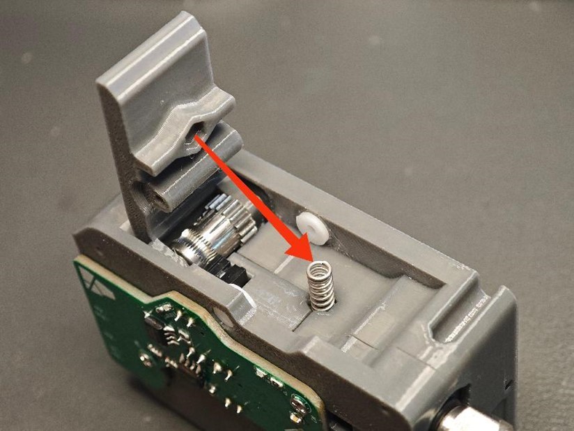
- Place the Small Spring
- Place a small spring (0.6 × 4 × 10mm) in the position shown in the diagram.
- Snap the wrench into place, ensuring the spring is properly seated and compressed.
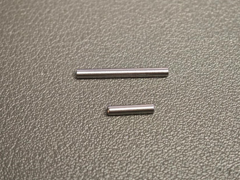
- Insert Short and Long Axles
- Use a short axle (D2 × 10mm) and a long axle (D2 × 20mm).
- Insert the short axle first, followed by the long axle, through the wrench holes into the axle sleeve.
- Verify smooth movement when pressed and rotated.
- Secure the Final Cover
- Adjust the motor wires, place the final cover, and secure it with four M2 × 8 self-tapping screws.
- The extrusion assembly is now complete.
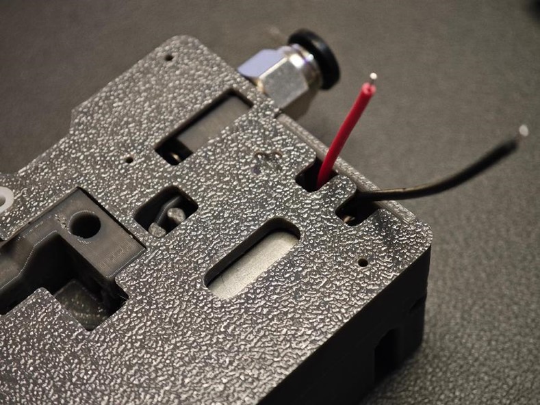
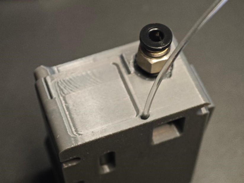
- Insert Transparent Material
- Insert transparent material into the indicated holes, ensuring it reaches the bottom, then cut it off.
- This will guide the indicator light.
¶ Step 3: Mechanical Assembly part 2 - Base Installation and Connections
-
Connect the Feeders
- Insert the PH2.0 10-pin male-to-male reverse cable (80mm in length) into the feeder interface.
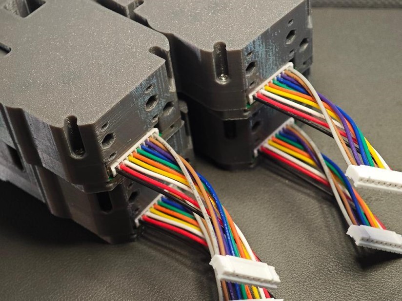
- Insert the PH2.0 10-pin male-to-male reverse cable (80mm in length) into the feeder interface.
-
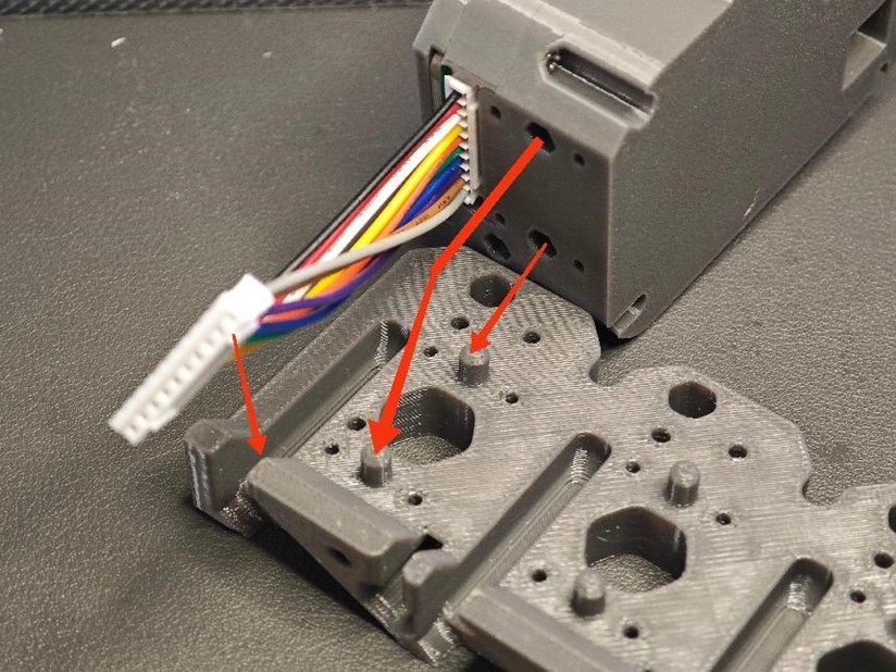
Install Feeders onto the Top Cover
- Attach the feeder units to the top cover of the base, aligning them with the designated holes.
- Place the cables into the wire grooves to keep them organized.
-
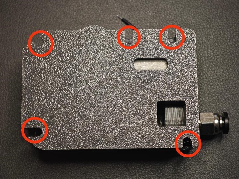
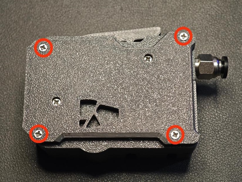
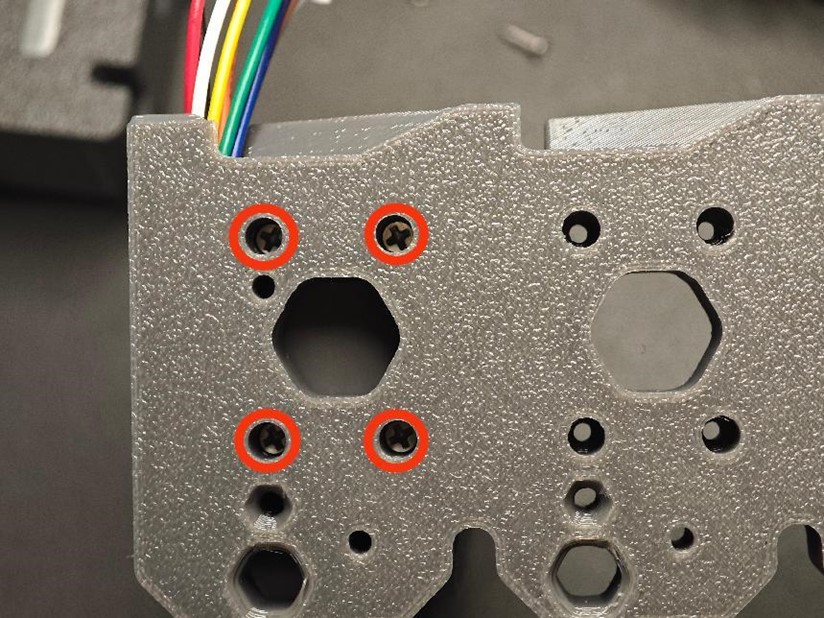
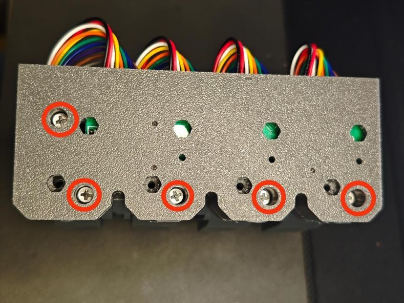
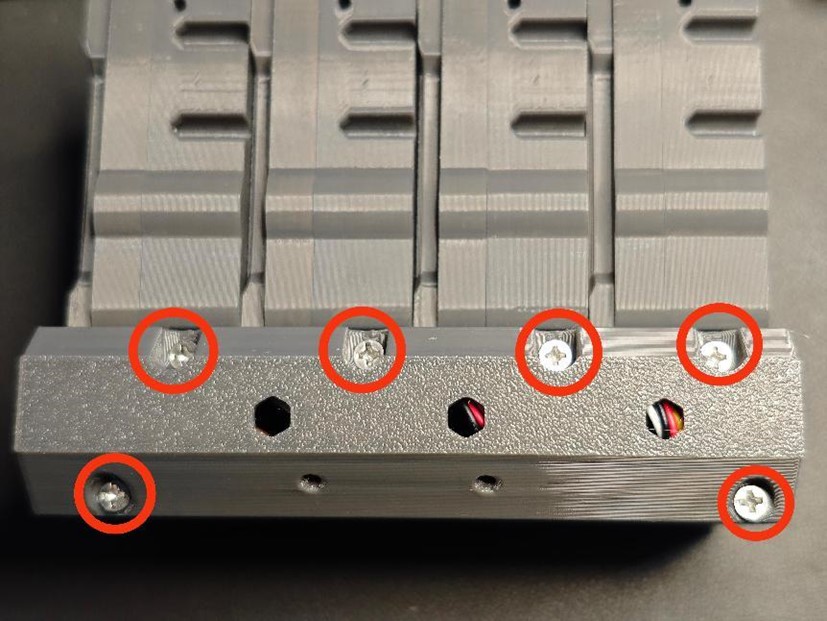
Secure Feeders
- From the underside of the top cover, tighten the screws (M2 × 8 self-tapping screws) at the red-circled positions.
- Repeat this process to secure all feeder units.
-
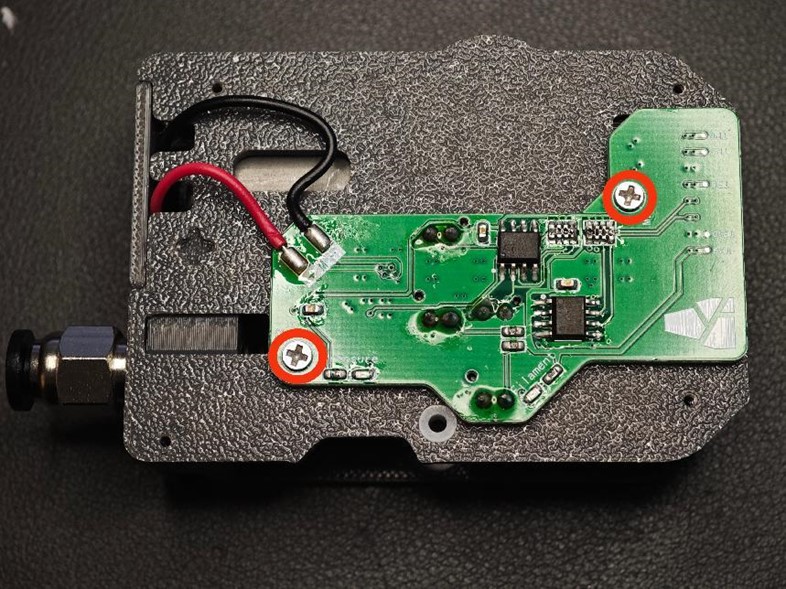
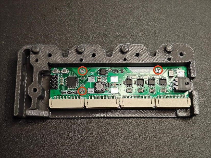
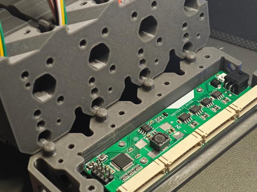
Mount the Mainboard
- Install the mainboard onto the base, aligning it with the red-circled screw holes.
- Secure it with M2 × 8 self-tapping screws.
-
Assemble the Base
- Combine the base parts as shown in the diagram.
- At the circled positions on the bottom of the base, secure it using M3 × 14 self-tapping screws.
-
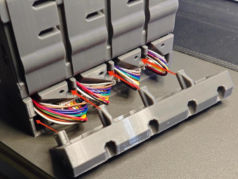
Connect Ribbon Cables and Finalize Assembly
- Insert the ribbon cables into their respective connectors.
- Place the wire cover over the cables and secure it at the circled positions with M3 × 14 self-tapping screws.
Before installing this cover, if you plan to install it on the printer immediately, please refer directly to the Mounting section
¶ Done! 
The BMCU complete system assembly is now finished.