¶ Preamble
The tutorials on this page are adapted to the following models posted on my makerworkd. Since there are numerous versions of motors for the housing that currently exists for the BMCU, this page only shares the versions of the models that I have found to work well along with their installation tutorials.
¶ Model
PLA/PETG or higher strength materials can be used.
Printing with PETG is more recommended. As well as PETG being slicker and in some cases easier to install.
It is easier to print with PLA for higher precision, but be careful not to use too much force when screwing.
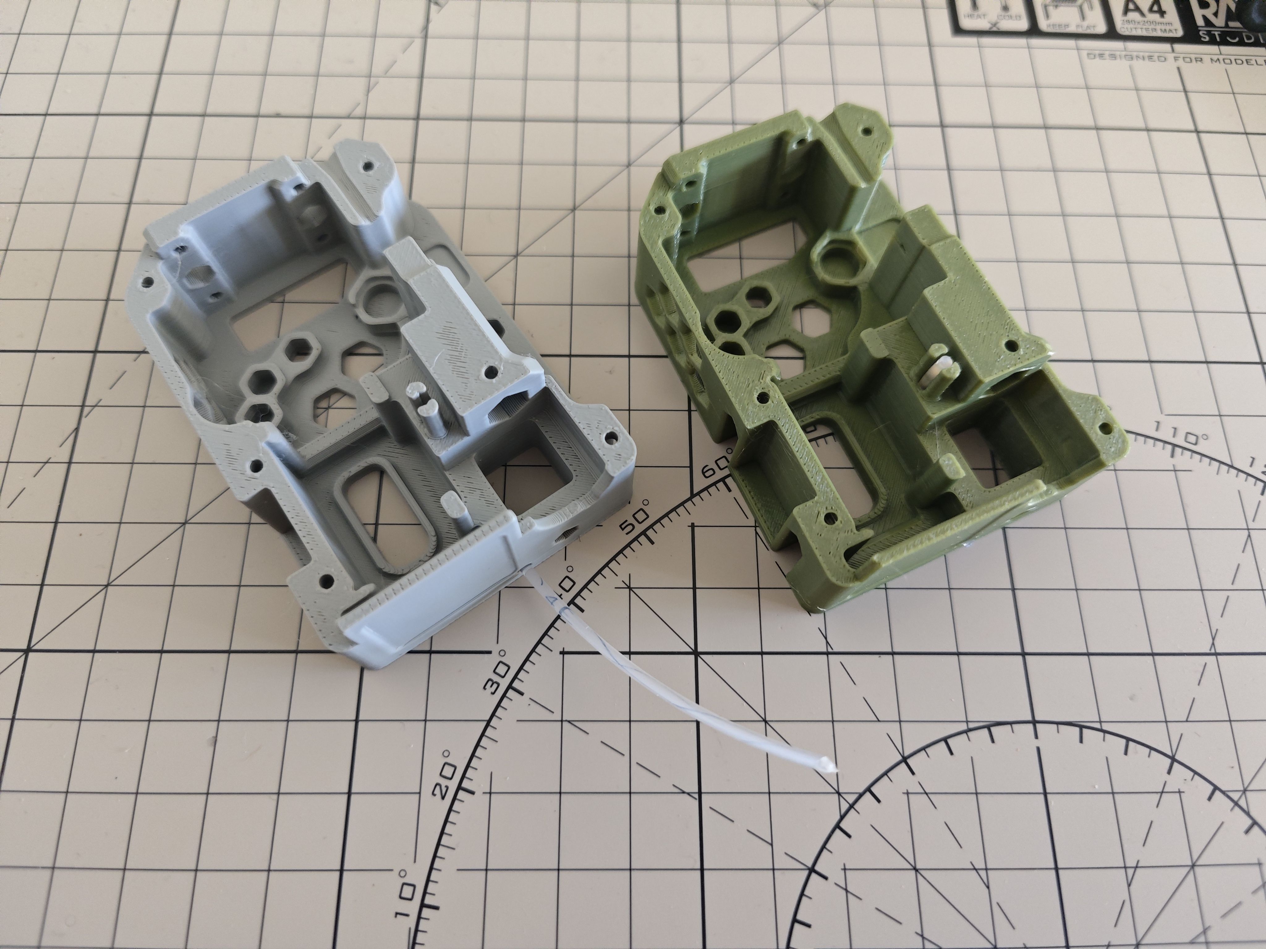
This model is characterised by:
- almost the original design of the author
- does not use the structure of the modular photoelectric sensor
- an optimised lever is used for easy mounting
¶ 130 version
¶ Step 1 (optional)
Insert the clear consumable through the centre frame and tuck it in firmly until he other end emerges from the middle of the frame.
If conditions permit, a 1.5mm fibre is recommended.
If you don't have transparent filament, skipping this step is not a problem. You can always do this step after the assembly is complete.
¶ Step 2
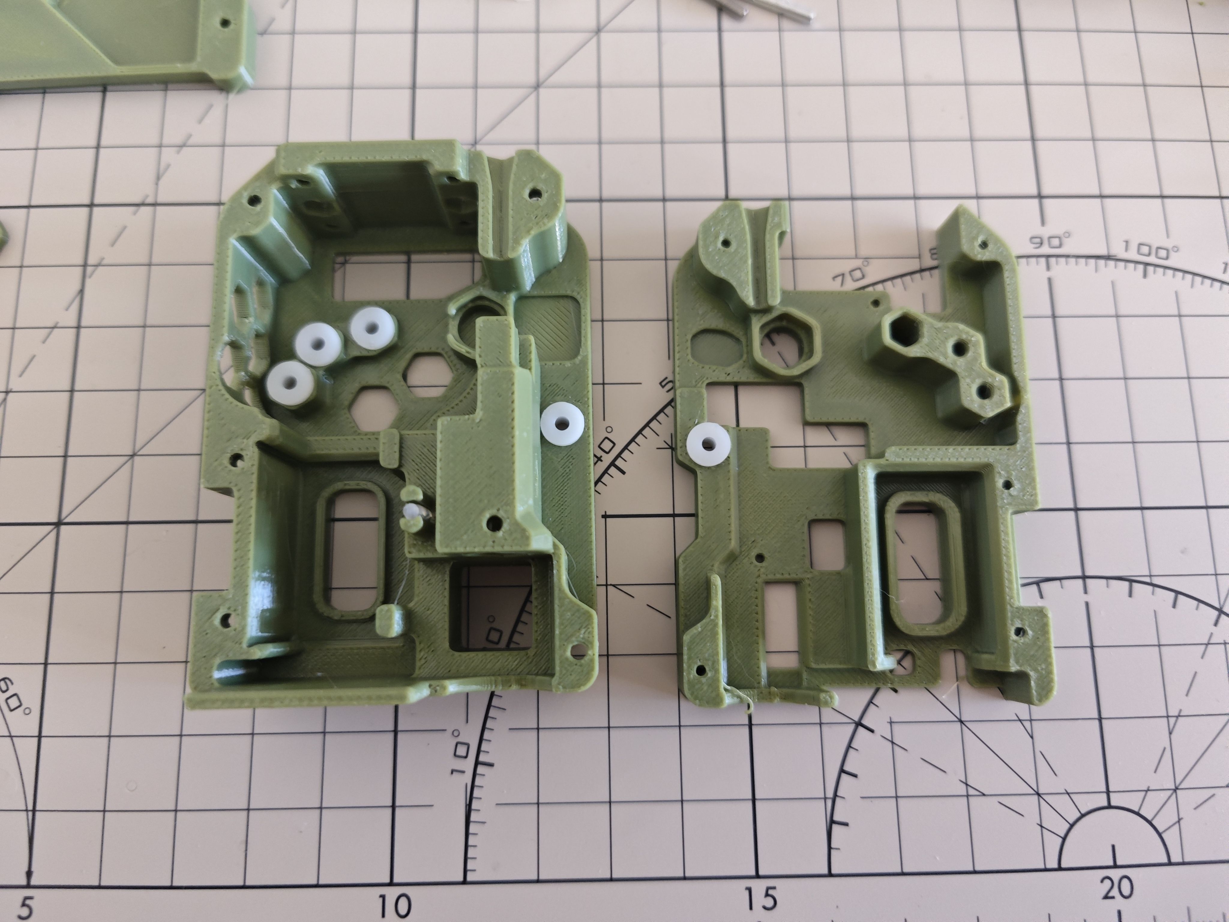
Approximate parts needed (this image may not be complete)
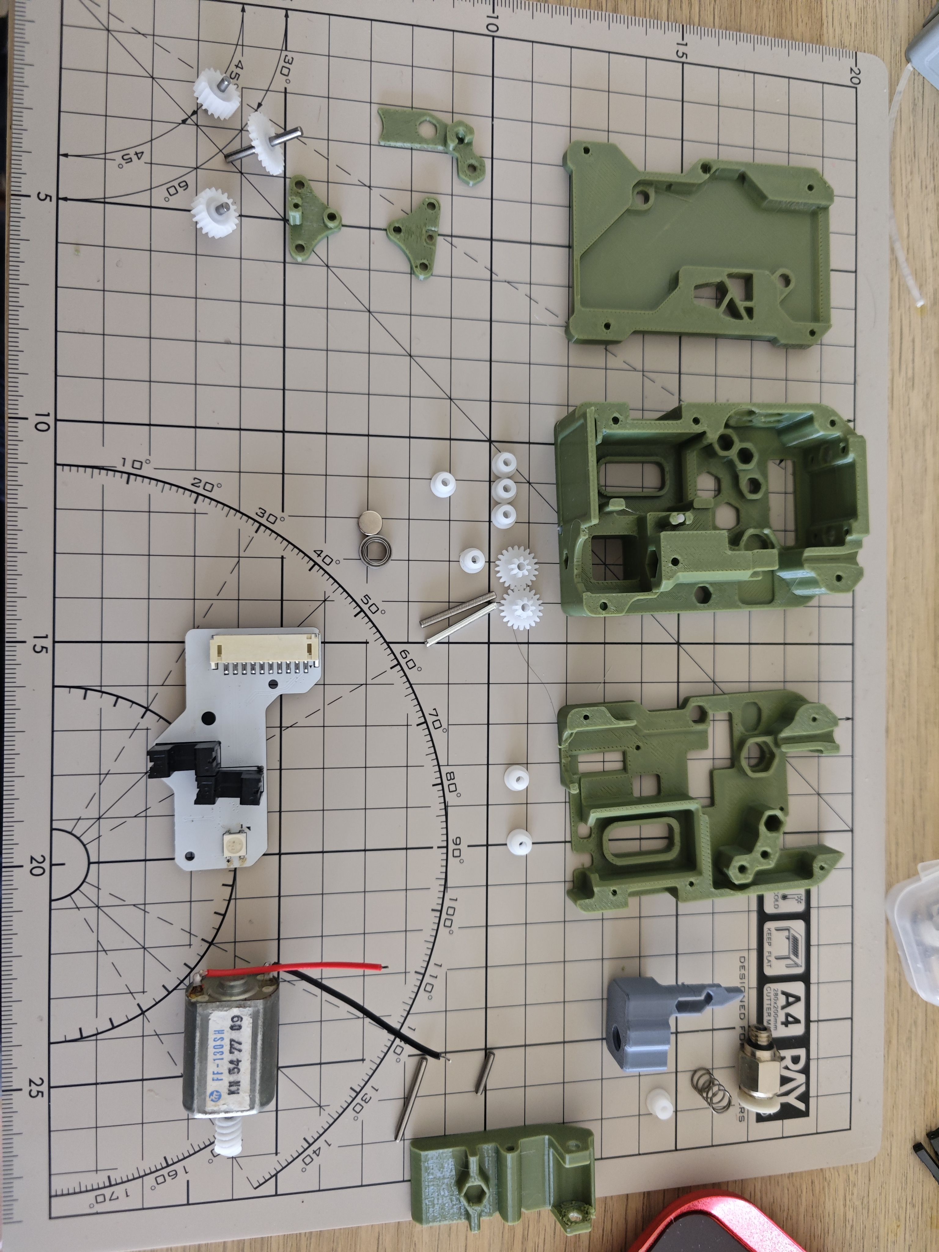
Install all 62B bushings
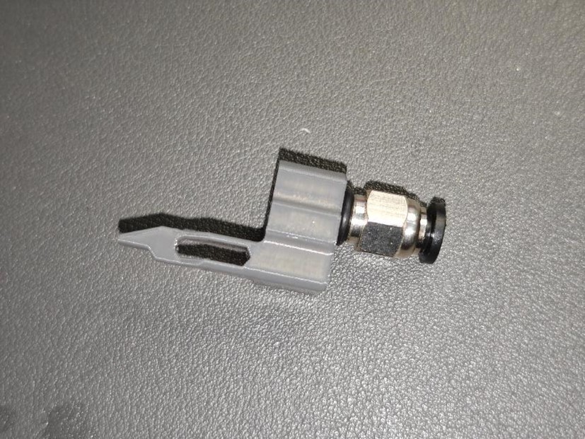
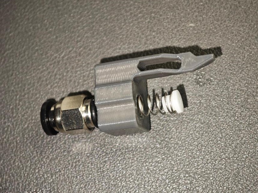
¶ Step 3 Attach the Pneumatic Fitting (PC4-M6)
- Screw the PC4-M6 pneumatic fitting into the buffer assembly.
- Caution: Ensure it is screwed in straight to avoid misalignment.
¶ Step 4 Assemble the Spring and the 62B Axle Sleeve
- Take one large spring (0.5 × 6 × 10mm) and a 62B axle sleeve.
- Assemble them as shown in the diagram below:
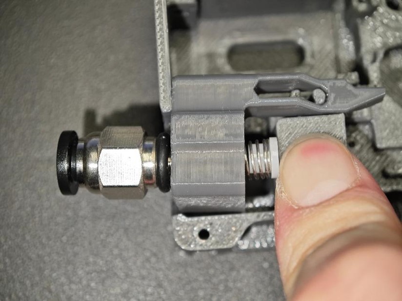
¶ Step 5 Compress the Spring and Snap it into the Base Housing
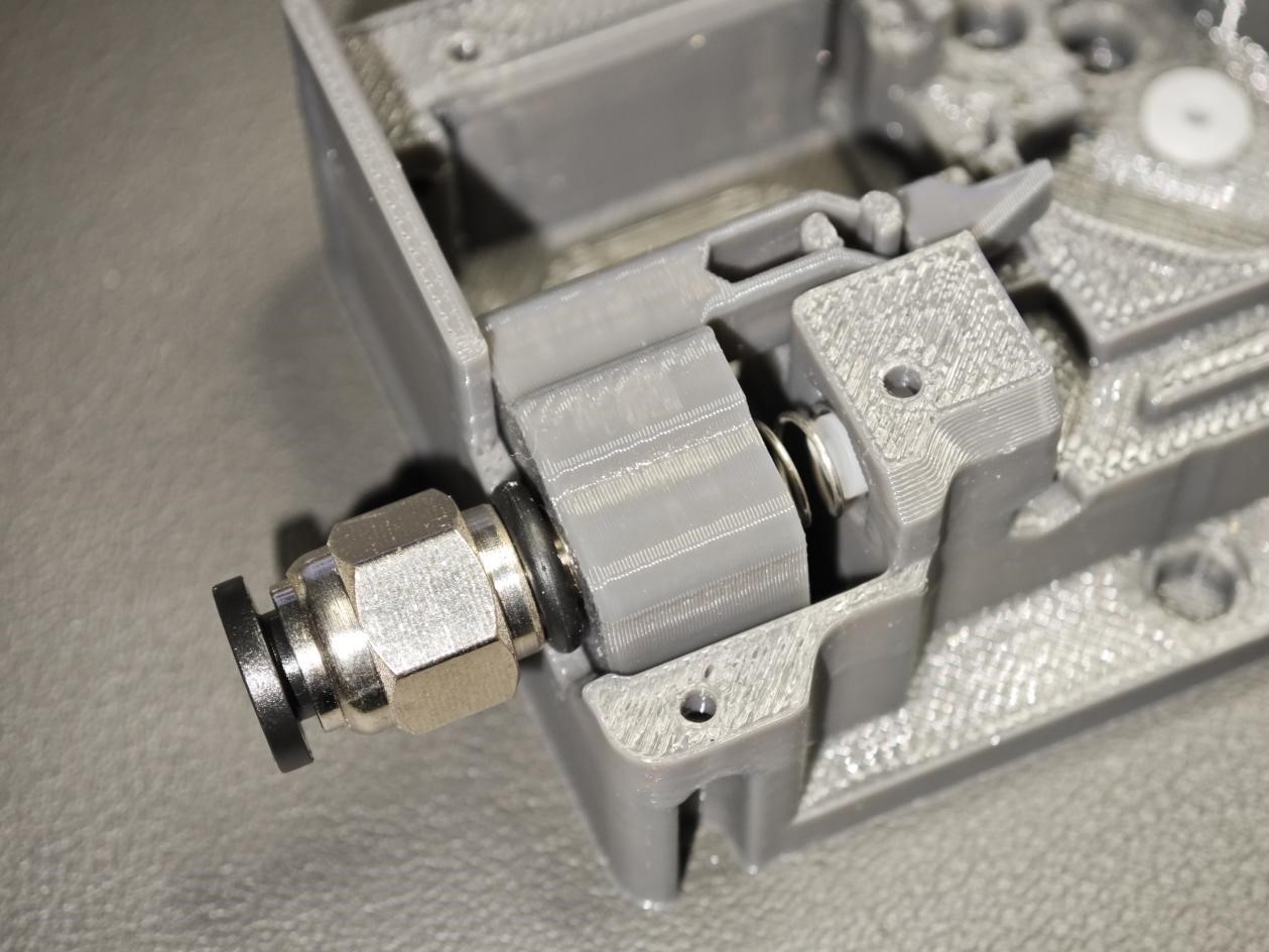
¶ Step 6 Ensure the Components Move Freely
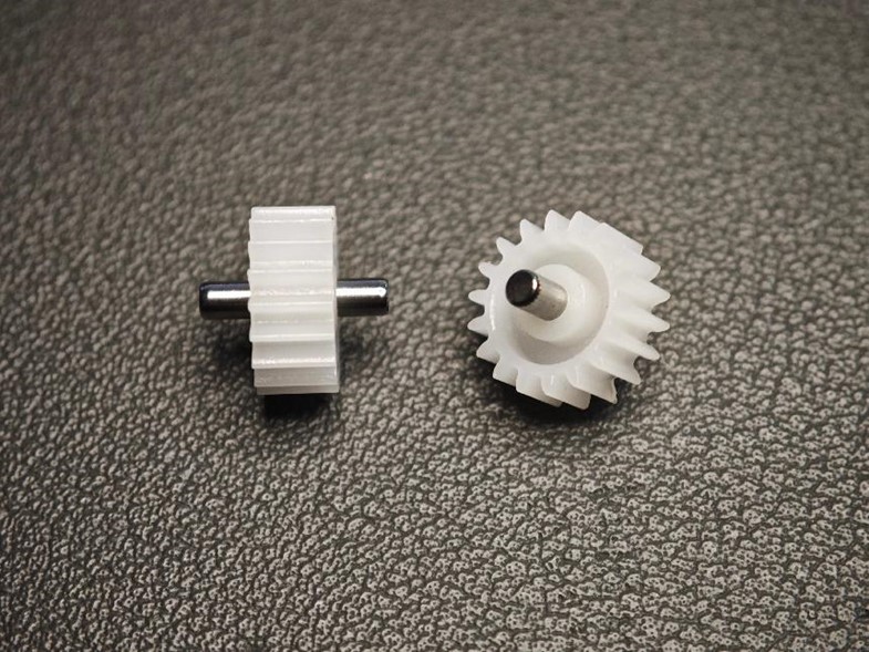
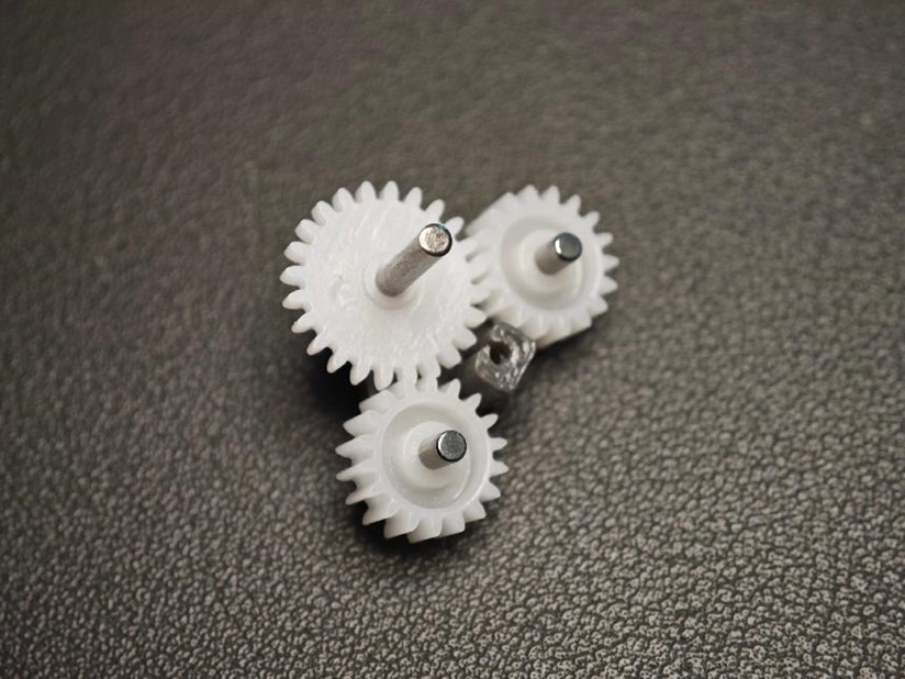
¶ Step 7 Assemble the Gear Structure
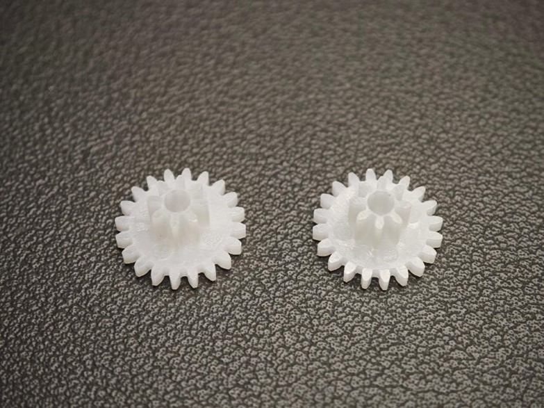
- Take two small gears (Gear 182A) and two short axle (2 × 10mm).
- Assemble them as shown in the diagram.
- Ensure the protruding sections on both sides of the axle are of equal length for proper alignment.
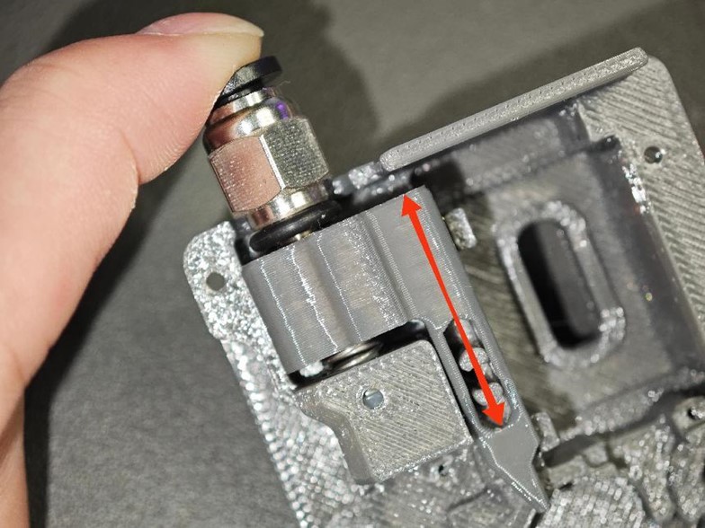
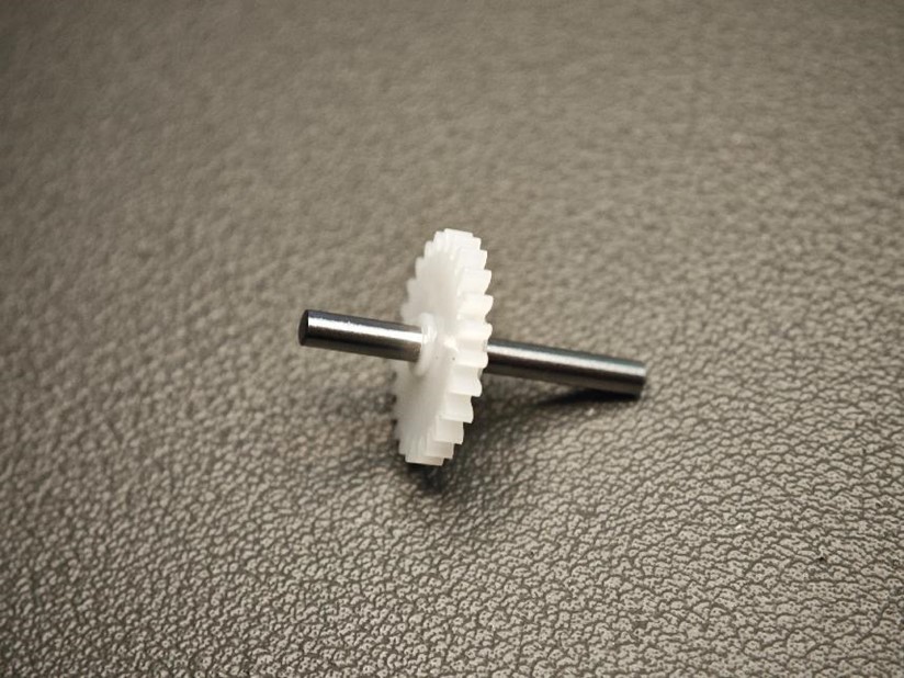
¶ Step 8 Assemble the Large Gear and Long Axle
- Take a large gear (Gear 242A) and a long axle (2 × 20mm).
- Assemble them to match the diagram, ensuring one end of the axle is pressed to the width indicated by the arrow in the diagram.
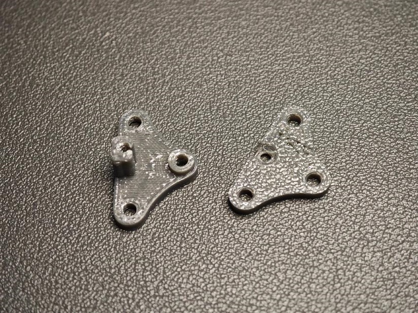
¶ Step 9 Select Two Triangular Parts
These two triangles are very difficult to print and mount, and you may want to print more than one at a time just in case.
Select a pair of triangular plates here
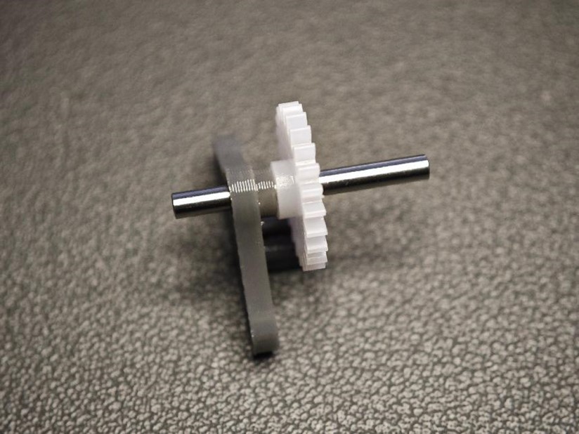
¶ Step 10 Assemble the Large Gear with the Triangular Parts
- Attach the large gear to the triangular parts as shown in the diagram.
- Important: Pay close attention to the orientation of the gear to ensure correct assembly.
¶ Step 11 Assemble the Remaining Small Gears and Secure the Components
- Attach the remaining two small gears to the structure.
- Place the cover over the assembly and tighten it using M2 × 8 self-tapping screws.
- Ensure all screws are securely fastened to maintain stability.
For the 130 version, this triangle is one of the most difficult to debug. It should turn smoothly, but also some resistance.
Make sure that the gears and shafts are not crooked when you install them.
If possible, apply a suitable amount of lubricant such as the one came with Bambulab printer, a damping grease with some viscosity is recommended.
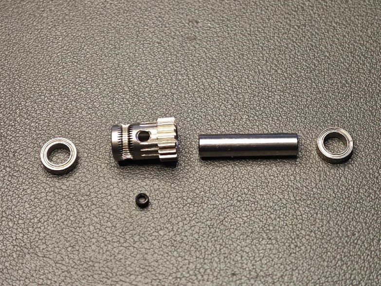
¶ Step 12 - Prapare BMG gear
A word of caution: please handle the combination of BMG gear set, D5*2 shaft and bearings with care, as the fit of the gears and shafts is sometimes very tight, and if it unfortunately gets stuck, it is very difficult to get it out again
Also they are quite expensive.
- Gather the following parts:
- Extrusion wheel with screw hole !!!!!! IMPORTANT
- Black set screw
- One thick axle (5 × 22mm)
- Two bearings (MR85ZZ).
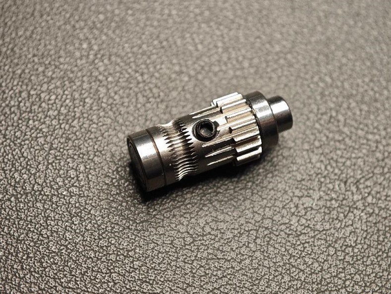
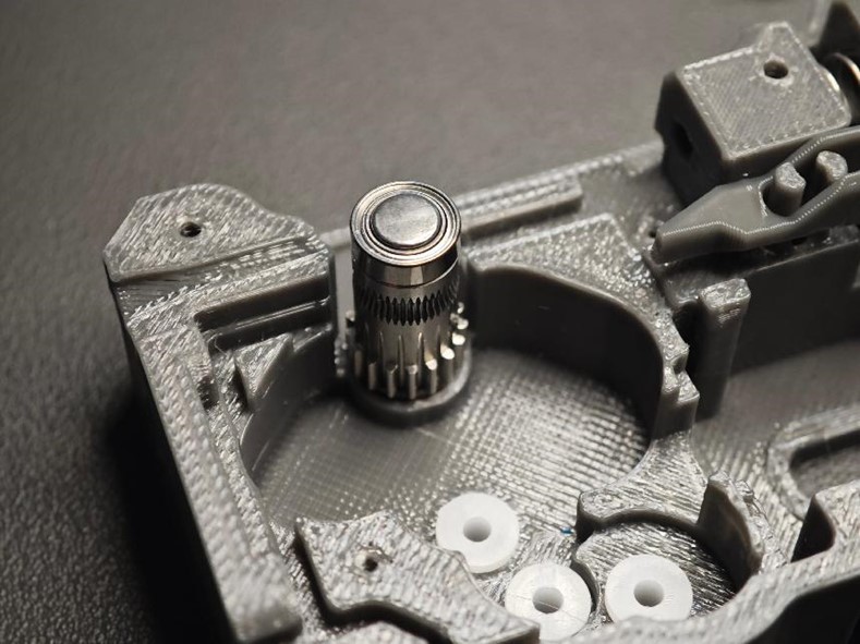
¶ Step 13 Assemble the Extrusion Wheel
- Assemble as shown in the diagram, paying close attention to orientation.
- One end of the thick axle must be flush with the bearing (to allow a flat surface for the magnet).
- Don’t forget to install the black set screw.
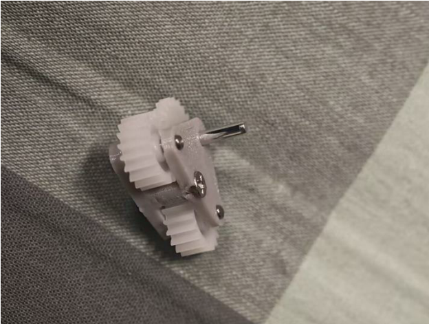
¶ Step 14 Place the Extrusion Structure
- Insert the extrusion structure into the base housing.
¶ Step 15
- Place the triangle group into the axle sleeves, ensuring the screw side faces downward, as shown in the diagram.
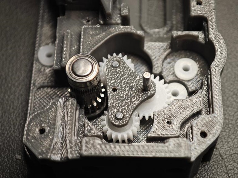
¶ Step 16
Install Two Long Axles
- Prepare two long axles (2 × 20mm).
- Insert them into the 62B axle sleeves.
- Install two 20082B double-layer straight gears, starting from left to right.
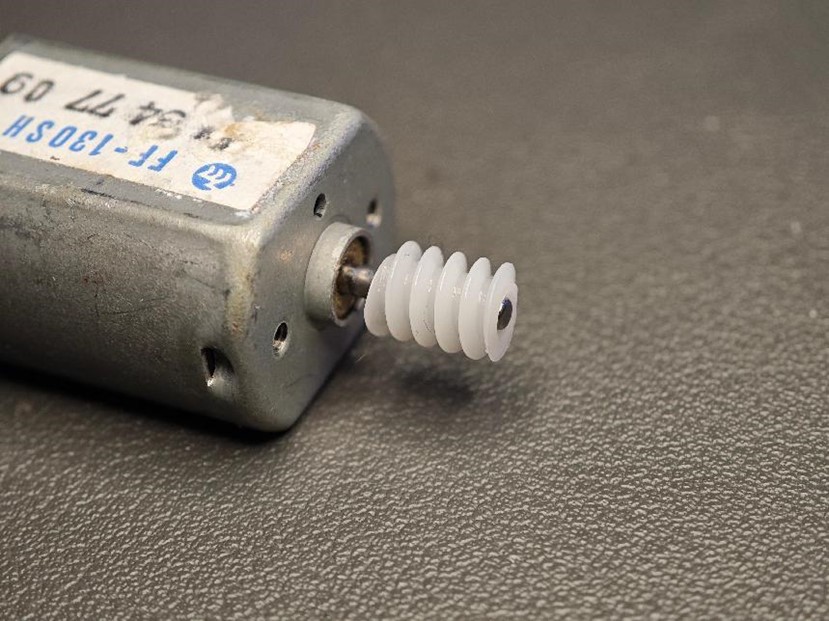
¶ Step 17 Assemble the Motor and Worm Gear
- Combine the FF-130 motor with the 682A worm gear.
- Ensure the assembly is flush; misalignment can cause gear jamming.
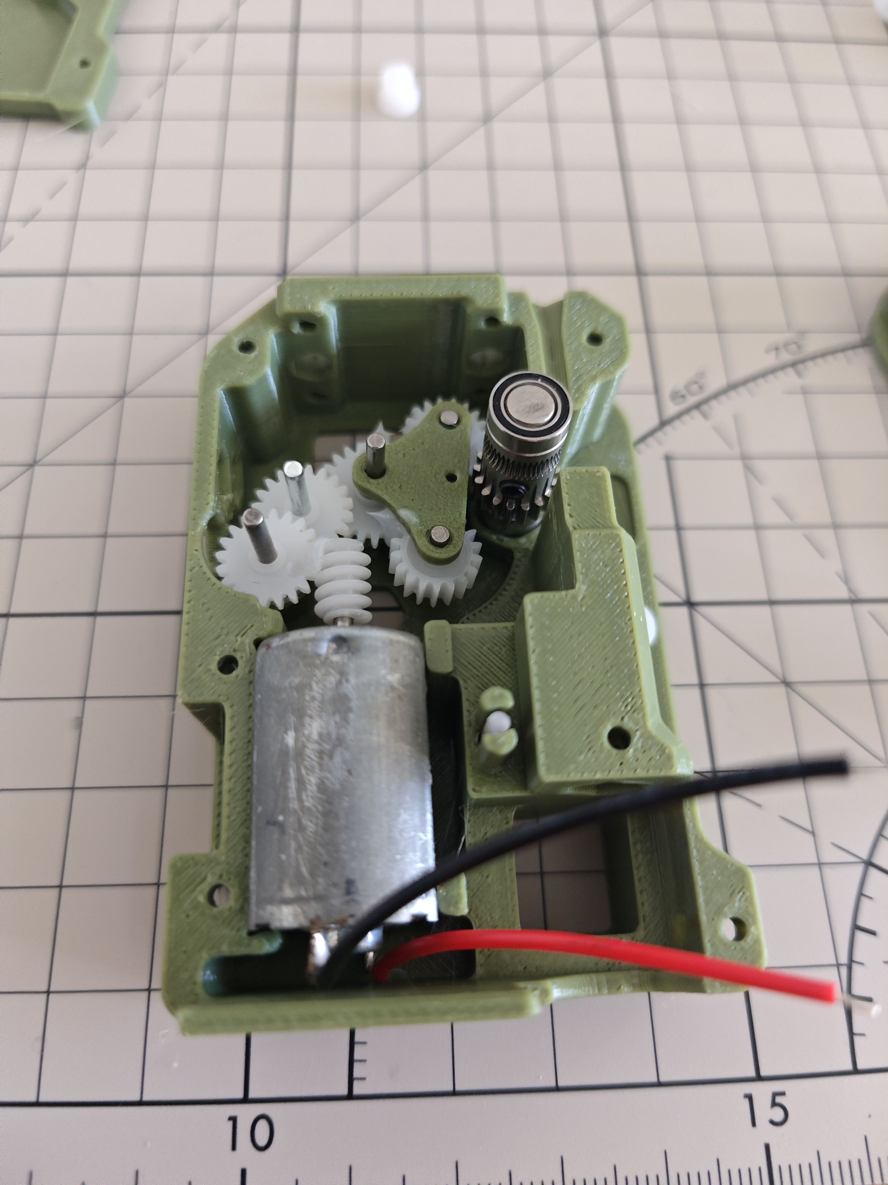
¶ Step 18
Install the motor in place. You can make soldering easier by keeping the red positive wire close to the pneumatic connector position
¶ Step 19
Install the gear holder as shown.
Install a 62B bushing on the long shaft of the triangular plate first
and then install the gear holder.
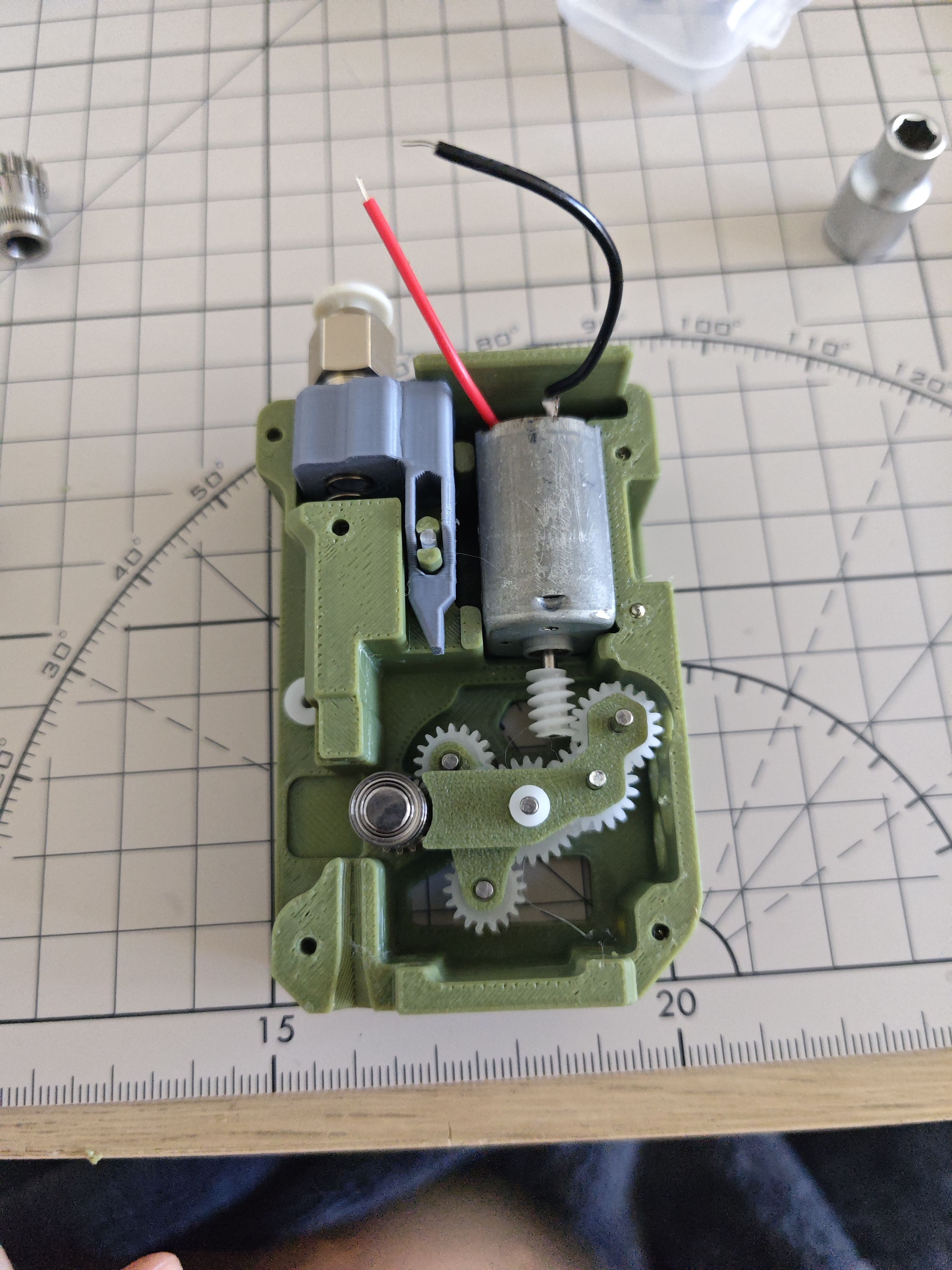
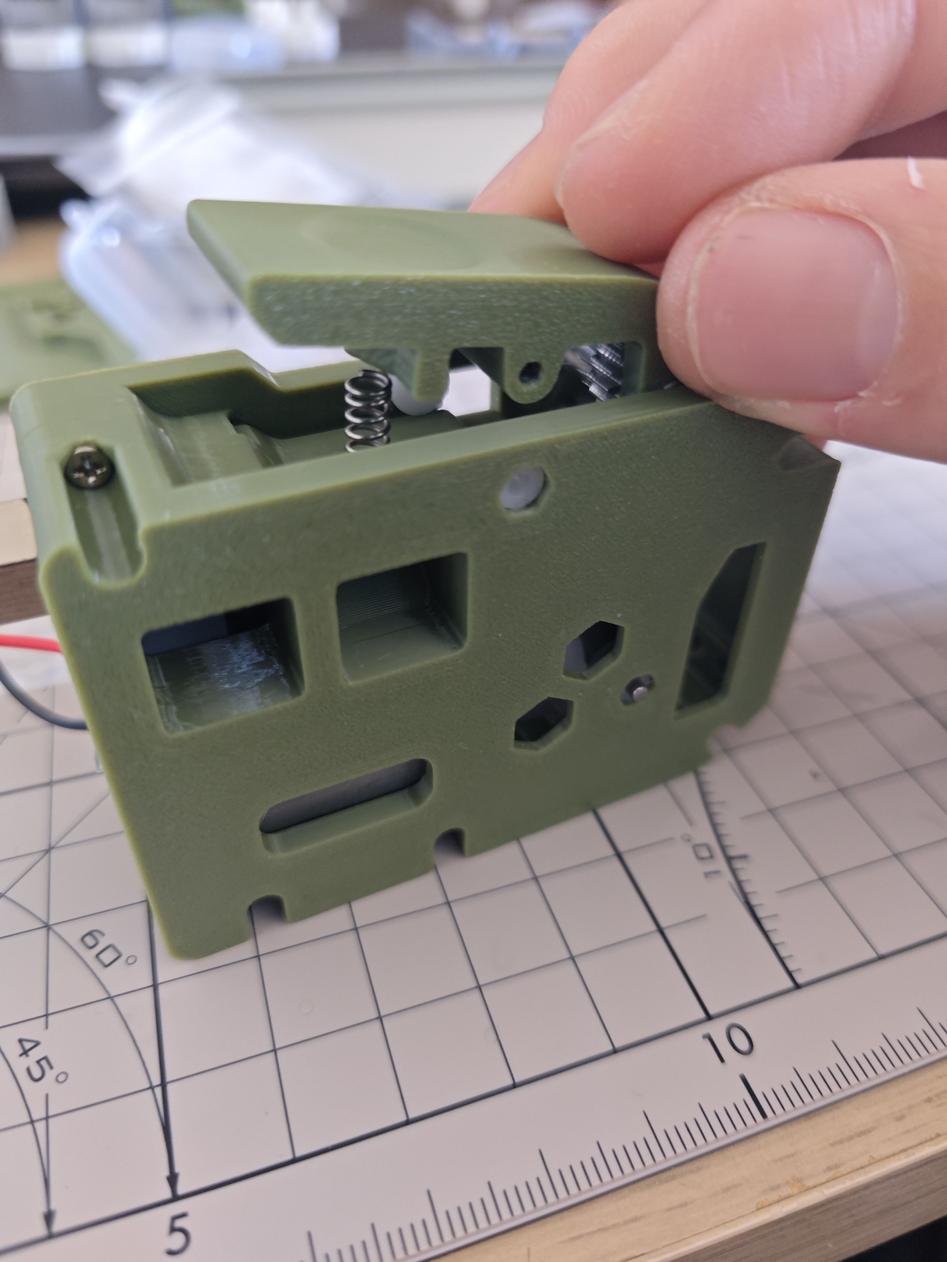
¶ Step 20
Install the cover plate by aligning its holes with a couple of long shafts and the BMG gear carrier, running the motor wires through the cover plate first and then installing it in place.
Place the 6x2.5mm radial magnet into the round hole.You should make sure that the magnet can rotate with the BMG gear set without jamming.
(I've used the pictures of the later steps to label this, it's normal that you haven't fitted spanners, shafts etc at this point)
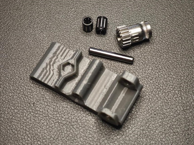
¶ Step 21 Prepare Remaining Components
You may need to sand or chip the side of this spanner where the support is added, you should make sure that after the shaft is inserted, the BMG gear set rolls very smoothly but does not shift.
- Gather the following parts:
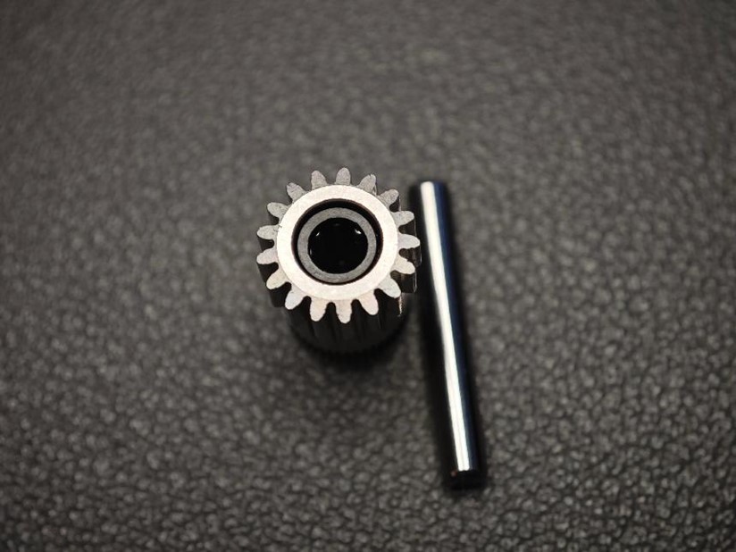
- Two needle roller bearings
- BMG-supplied axle
- Non-perforated extrusion gear
- Printed wrench.
- Assemble as shown in the diagram, ensuring the correct orientation.
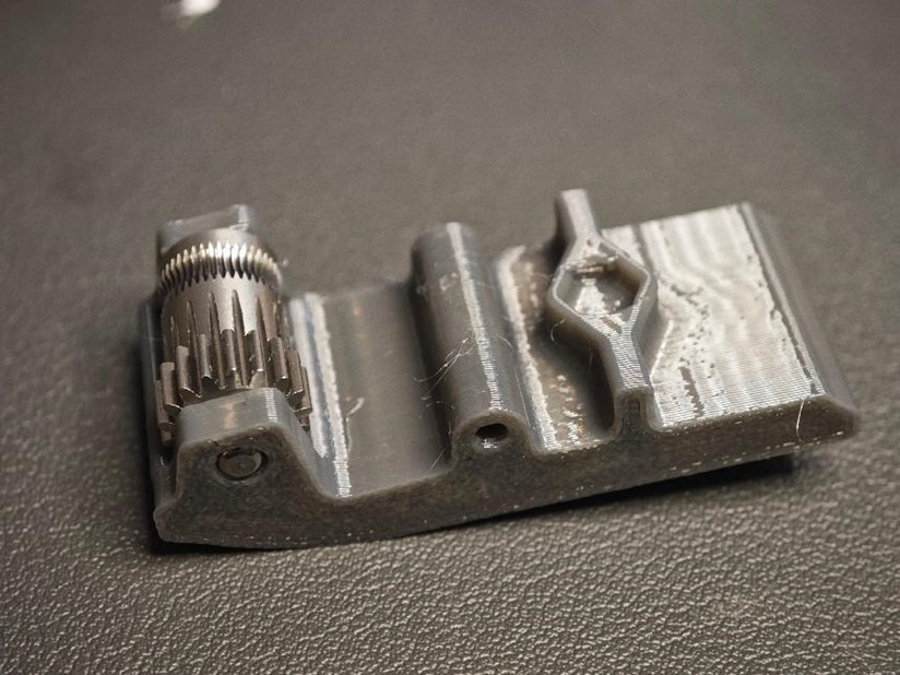
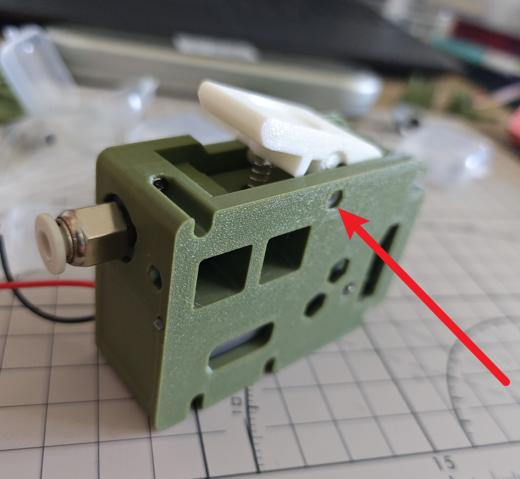
¶ Step 22
Place a small spring, then press the spanner after aligning the empty space of the spanner with the spring
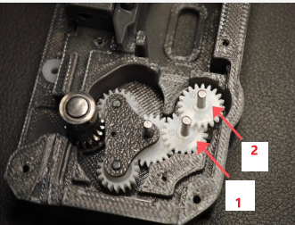
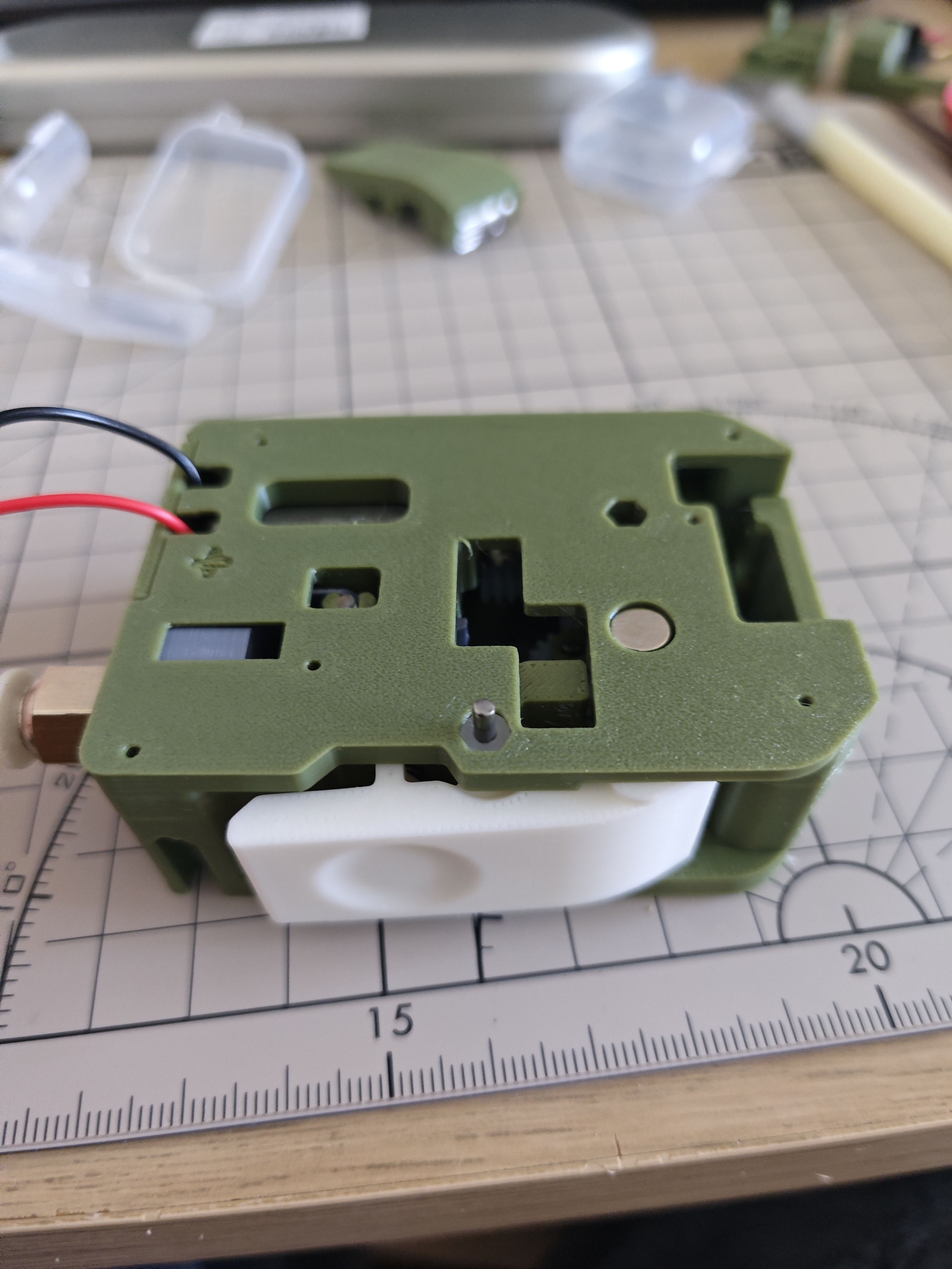
¶ Step 23
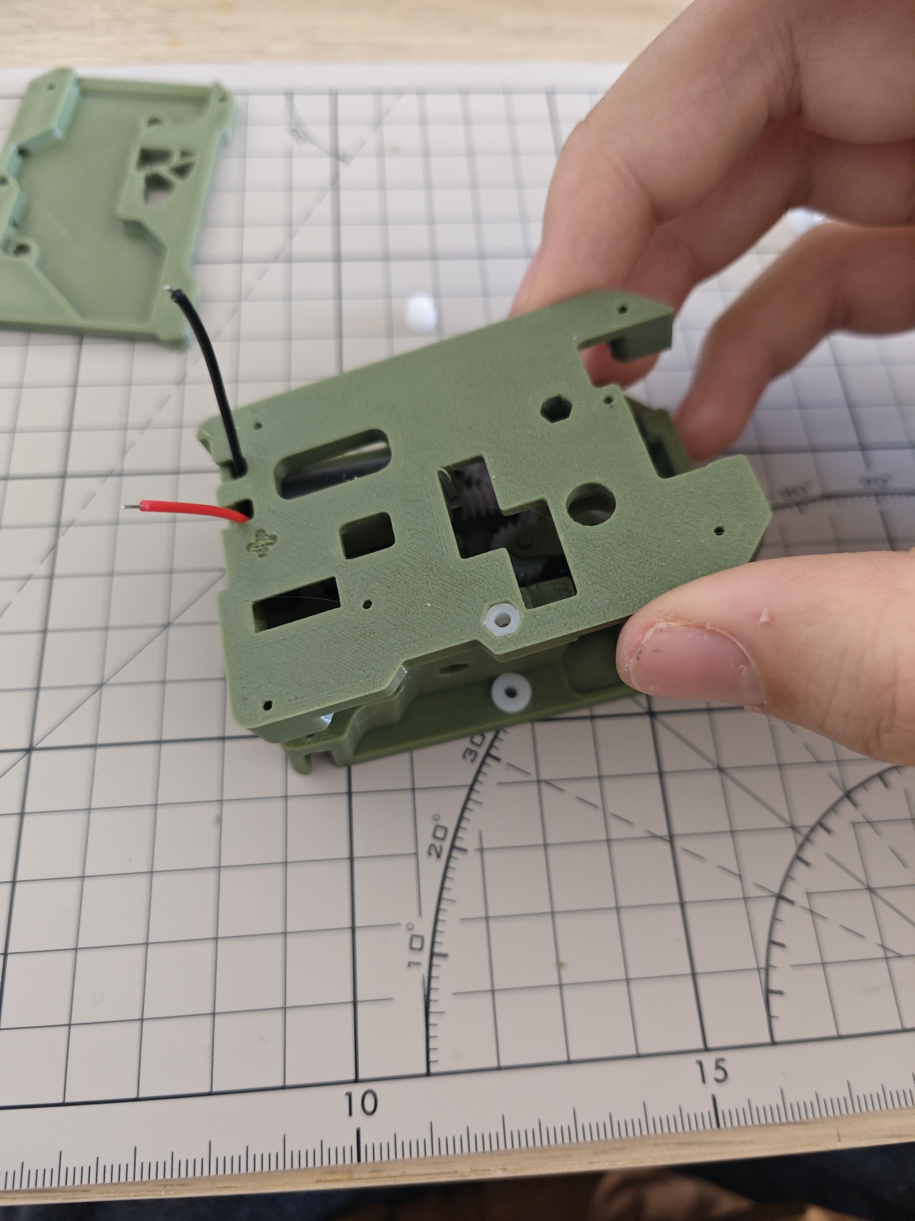
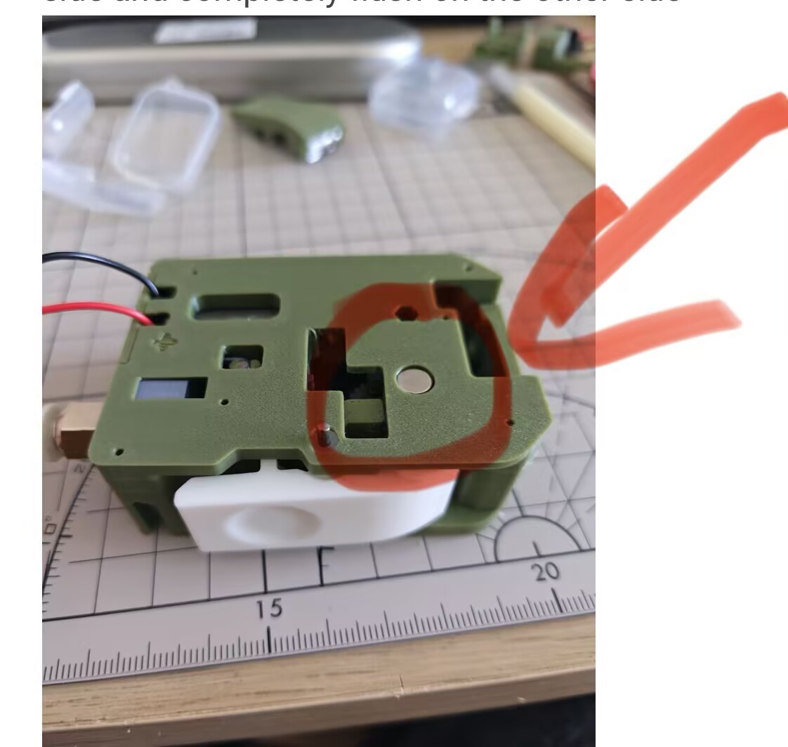
Use one long shaft + one short shaft (or three short shafts) to insert into this hole.
In the author's original design, one side here is closed without the 62B bushing and hole, resulting in an inconvenient installation. This has been optimised here, which leads to the possibility of not having enough long shafts, so if this is the case, three short shafts can be used for mounting.
You should end up with the shaft protruding a bit on this side and completely flush on the other side
¶ Step 24 Do a test 1
At this point, if you connect about 9v to the motor, you should be able to see smooth operation.
Insert a filament and it should be able to move and transport the filament.
You should also see the magnet rotating very smoothly. If the magnet is not rotating properly, adjust its position.

¶ Step 25
Use two M2x6 (or m2x8) screws to mount the sub-board, and solder the power cable according to the electrodes on the sub-board.
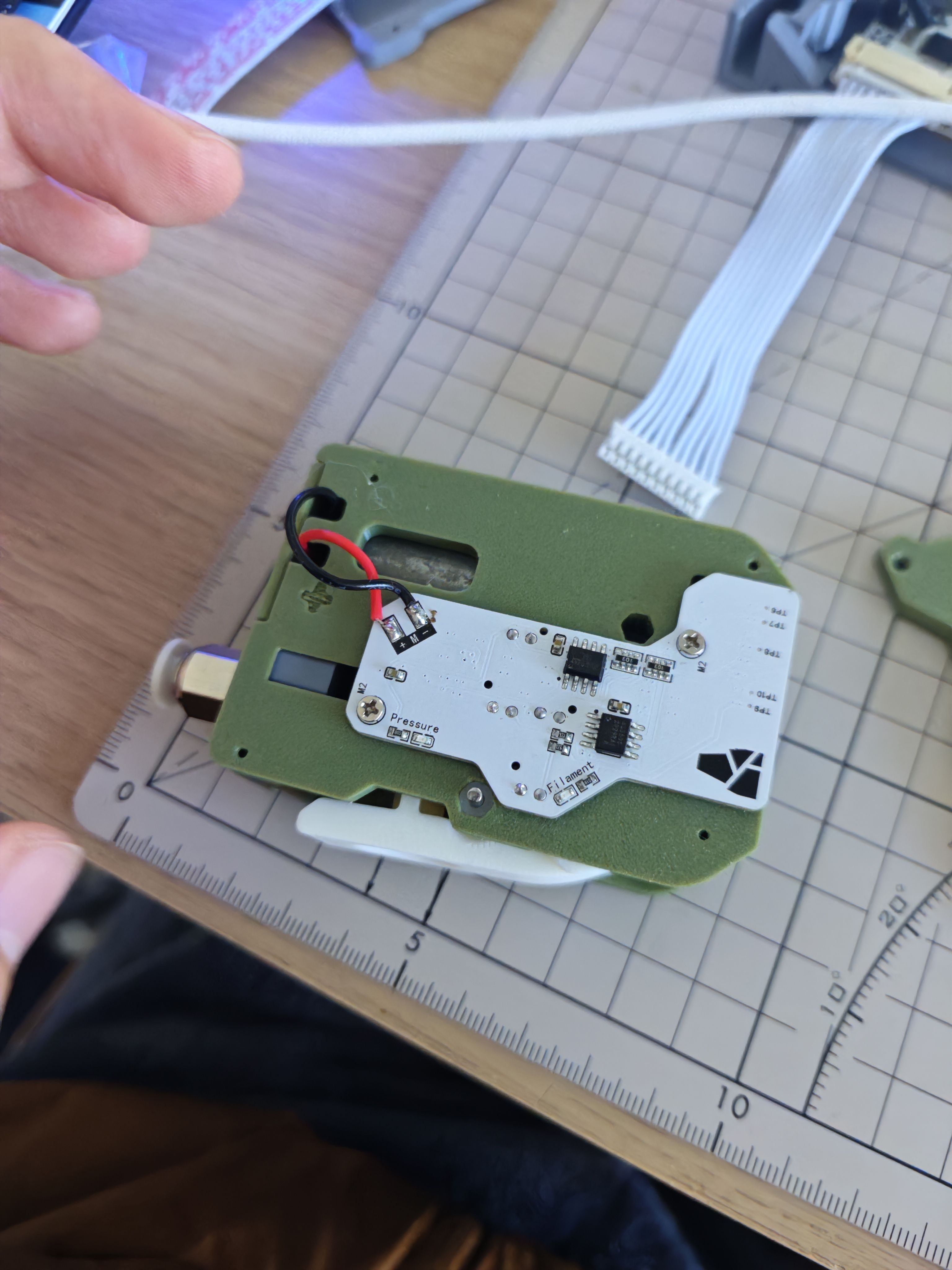
¶ Step 26 Do a test 2
Connect the mainboard to the computer via the usb serial port and connect the sub-board to the mainboard for power supply.
A red led should light up when you press the pneumatic connector.
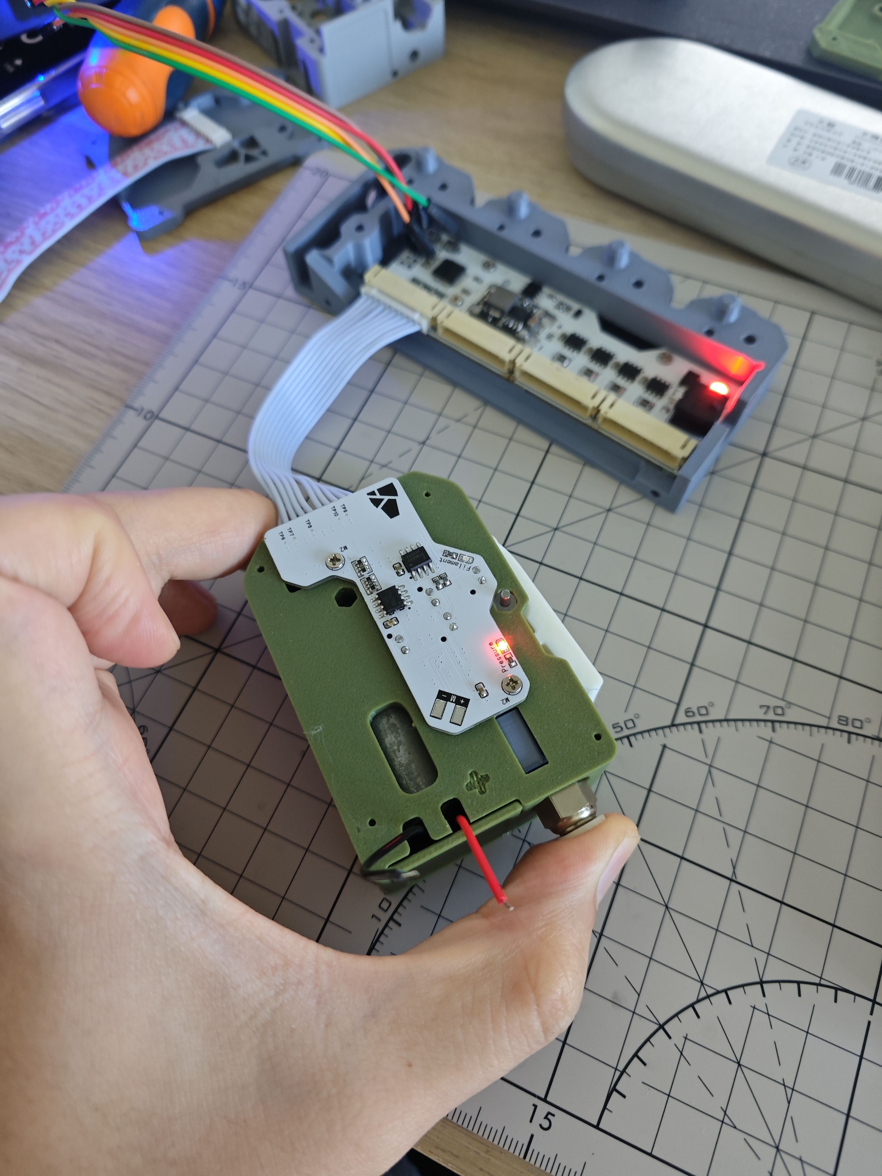
When you press the spanner to insert a section of filament, another red led should light up. This led should remain lit steadily while moving the consumables.

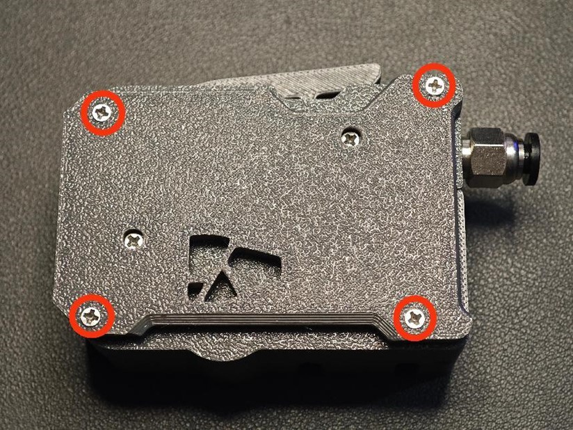
¶ Step 27 Secure the Final Cover
- Adjust the motor wires, place the final cover, and secure it with four M2 × 8 self-tapping screws.
- The extrusion assembly is now complete.
¶ After this steps are the same, please check the other tutorials
END