¶ 180 BMCU Assembly Guide
This content is made by
@白小淘
¶ Materials Preparation (excluding 3D printed parts):
The 180 version is modified from the 130 version, with an identical PCB. For PCB information, please refer to the 130 guide.
Changes in the materials list are minor, so only the differences from the 130 version are noted here. Please check the 130 guide for the full list.
Material changes are as follows:
- The original
130 motoris replaced with a180 motor. It is recommended to purchase 180 motors with a shaft length of 10mm-12mm. Most 180 motors rated at 12V-24V should work. Recommended link:- PWN17VEE12JA1 https://item.taobao.com/item.htm?_u=qu6u6p3c2bf&id=650572440927&spm=a1z09.2.0.0.7c412e8dH0f2vw Price at the time of writing: 1.8 RMB.
- FK-180SH-12280 (significantly increased in price)
- Buffer spring changed to
0.5 x 6 x 15mm, quantity:4. Purchase link: https://detail.tmall.com/item.htm?_u=qu6u6p36069&id=649882524891&spm=a1z09.2.0.0.4d042e8dhdKyYV&skuId=4728198936063 - Added clutch spring, specification
0.4 x 3 x 5mm, quantity: 4. Purchase link: https://detail.tmall.com/item.htm?_u=qu6u6p36069&id=649882524891&skuId=4686949972659&spm=a1z09.2.0.0.4d042e8dhdKyYV M2x5countersunk self-tapping screws are used in the 180 assembly guide, quantity: 16. If not purchased, you can use M2x8 from the 130 guide as a substitute.
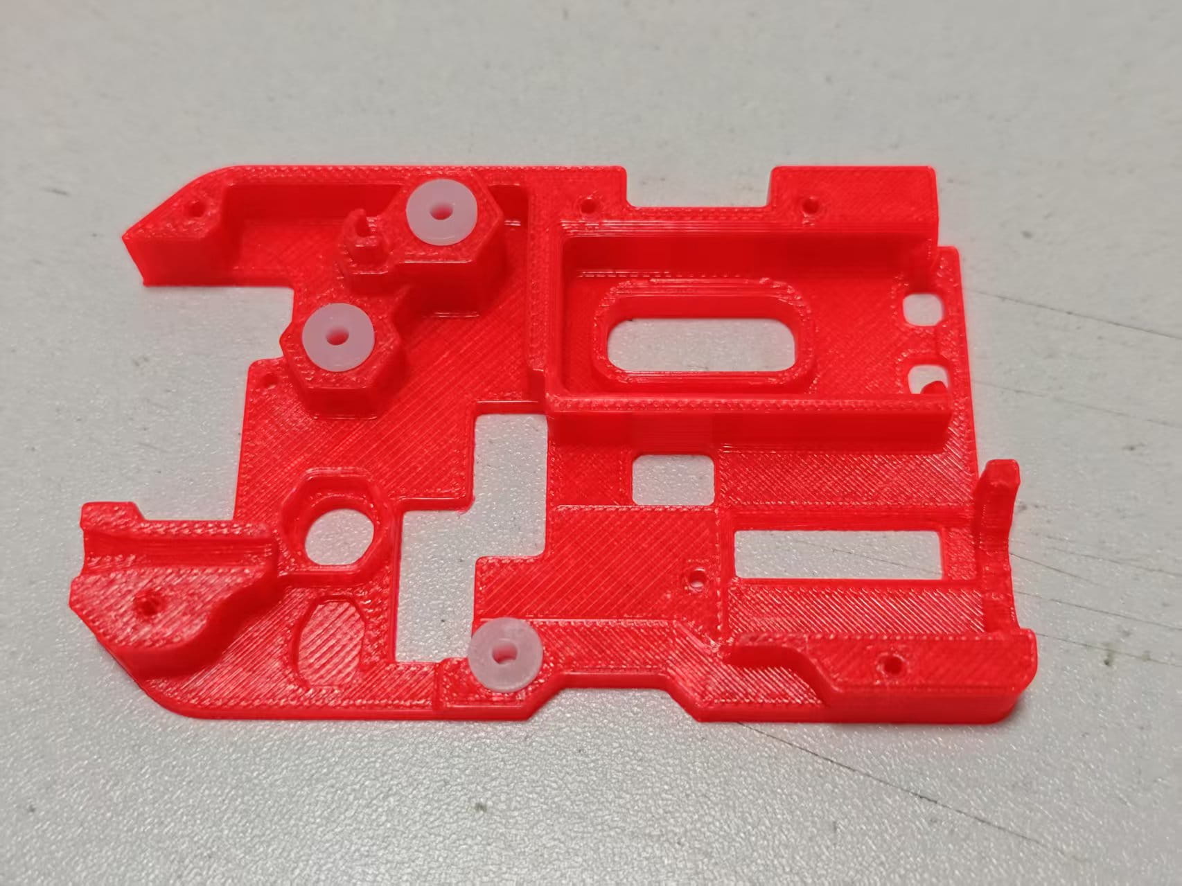
¶ 3D Printed Shell Files:
The shell has been completely redesigned and needs to be fully printed.
Version 1 is only suitable for 180 motors with a full metal shell. If you purchased the recommended PWN17VEE12JA1 motor from the link above, you need to print Version 2.
If you have no specific requirements or don't know the difference between the two versions, please print Version 2.
Note from Yuekai : Please print version 2.
Version 1: https://makerworld.com/zh/models/1132822#profileId-1133350
There are two print configurations in Version 1. The first configuration is a complete set of component models, print 4 sets. The second configuration contains only the "Clutch Part B - 4mm Thick 242A", suitable for 4mm 242A gears. The parameter in the 242A gear purchase link shows a 4mm thickness, but the actual received thickness is 3.2mm. If you do get a 4mm 242A gear, use the Clutch Part B from the second configuration.
Version 2: https://makerworld.com/zh/models/1152568#profileId-1156984
Note from Yuekai : Backup download link 180 version
Version 2 updates the appearance and removes some features that block the plastic rear cover of the 180 motor, making it compatible with both full metal and plastic rear cover 180 motors. The print configuration includes a complete component set and an installation aid.
If this is your first time assembling the BMCU, you will also need the base and bracket. Please use the base and bracket files from the group file "BMCU Integrated Package V1.1".
Note from Yuekai : For the base you can refer to this model, you can choose between the original version base in plate 2 or a newer version base similar to 370 version in plate 6
https://makerworld.com/zh/models/1162813-bmcu-130-version-an-optimized-extruder-search-comb#profileId-1291386
¶ Component Assembly:
The buffer lengths of the two versions are different. The motor mount of Version 2 is larger than that of Version 1. Other aspects are the same. The tutorial uses Version 2.
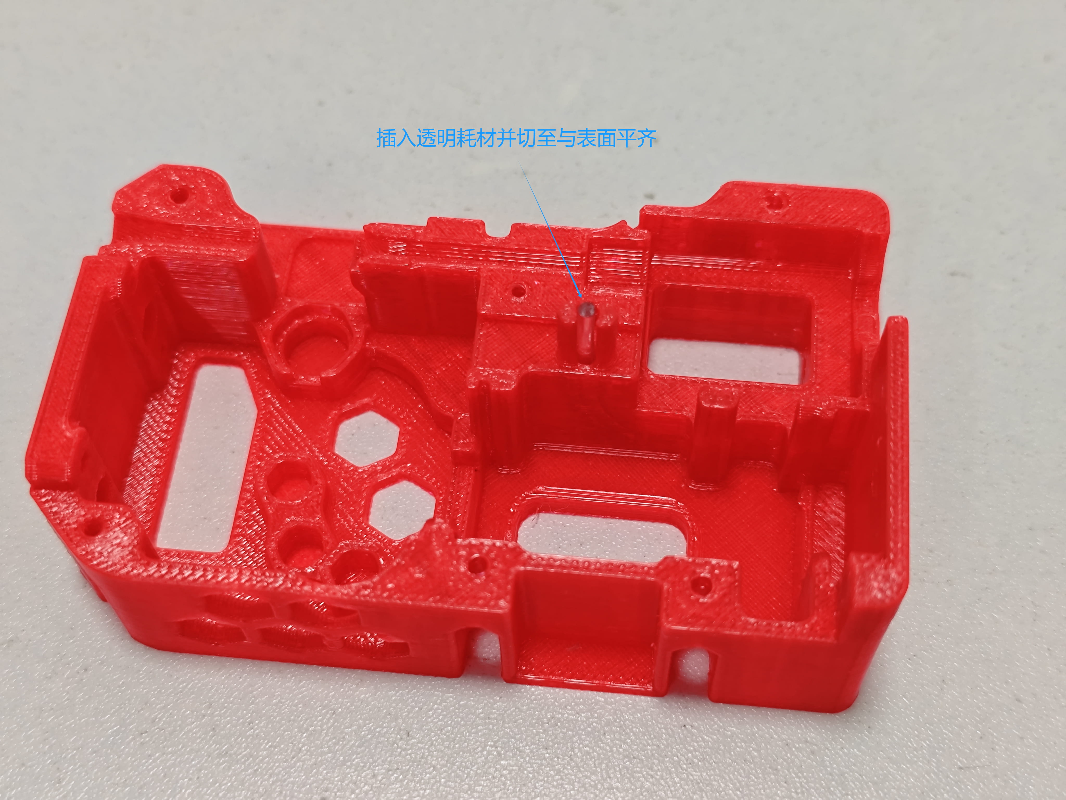
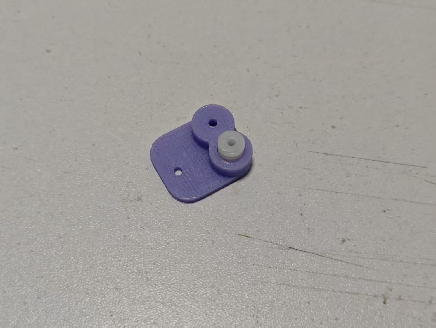
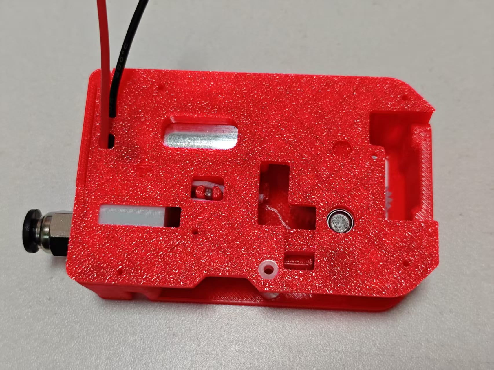
- Take out the bottom cover and insert transparent filament into the LED hole. Cut both ends flush with the surface.
Text on the picture: Insert the filament flush with the housing
-
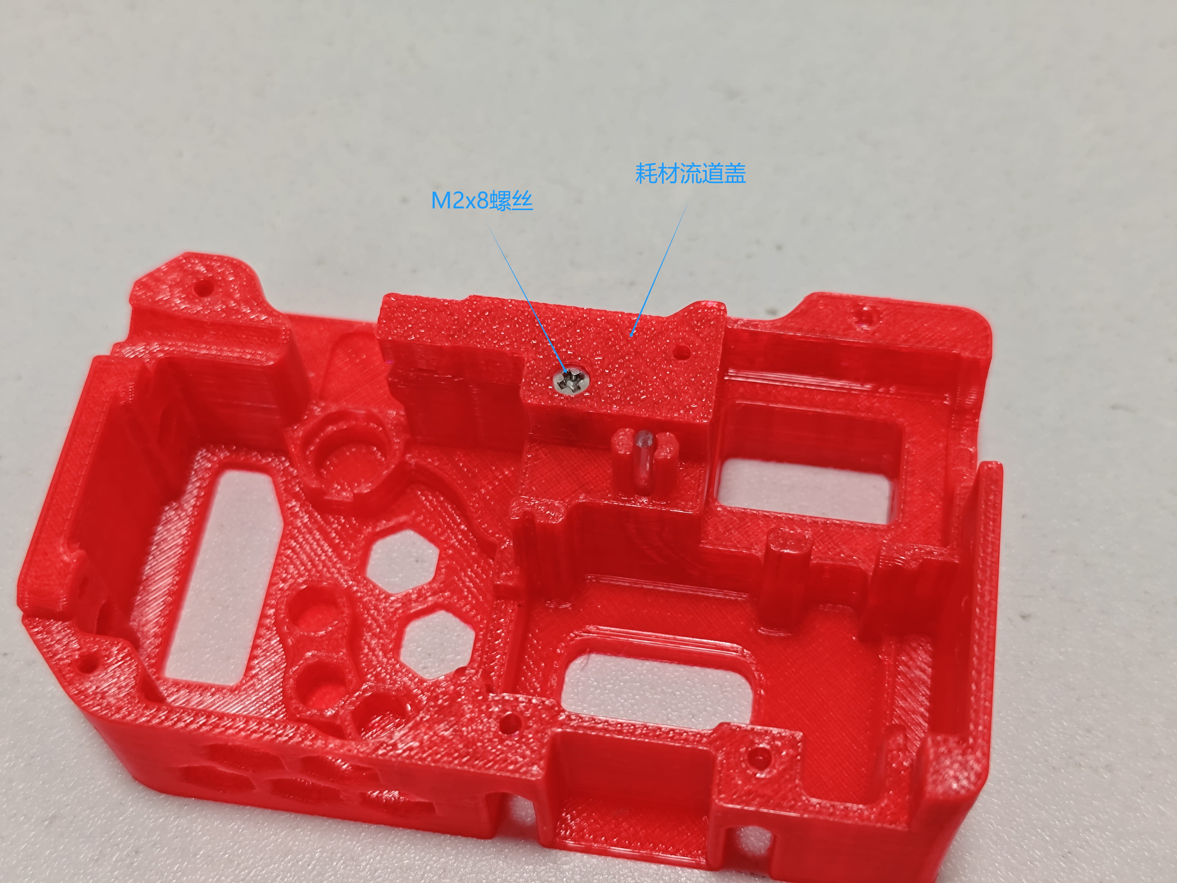
Fix the filament channel cover to the bottom cover with M2x8 flat head screws.
-
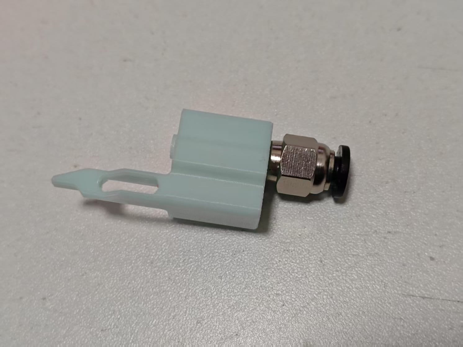
Screw the M6 pneumatic connector onto the buffer.
-
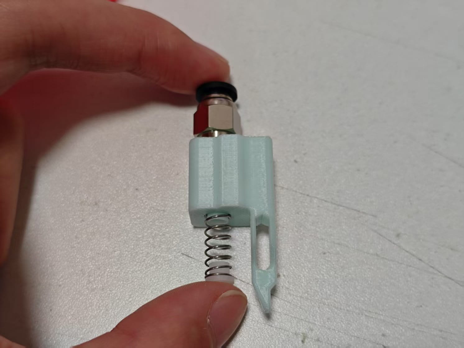
Place a 0.5x6x15mm spring onto the buffer, then place a 62B bushing. Pinch them together and install onto the bottom cover.
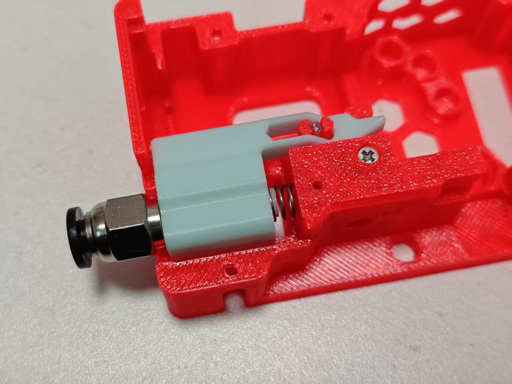
-
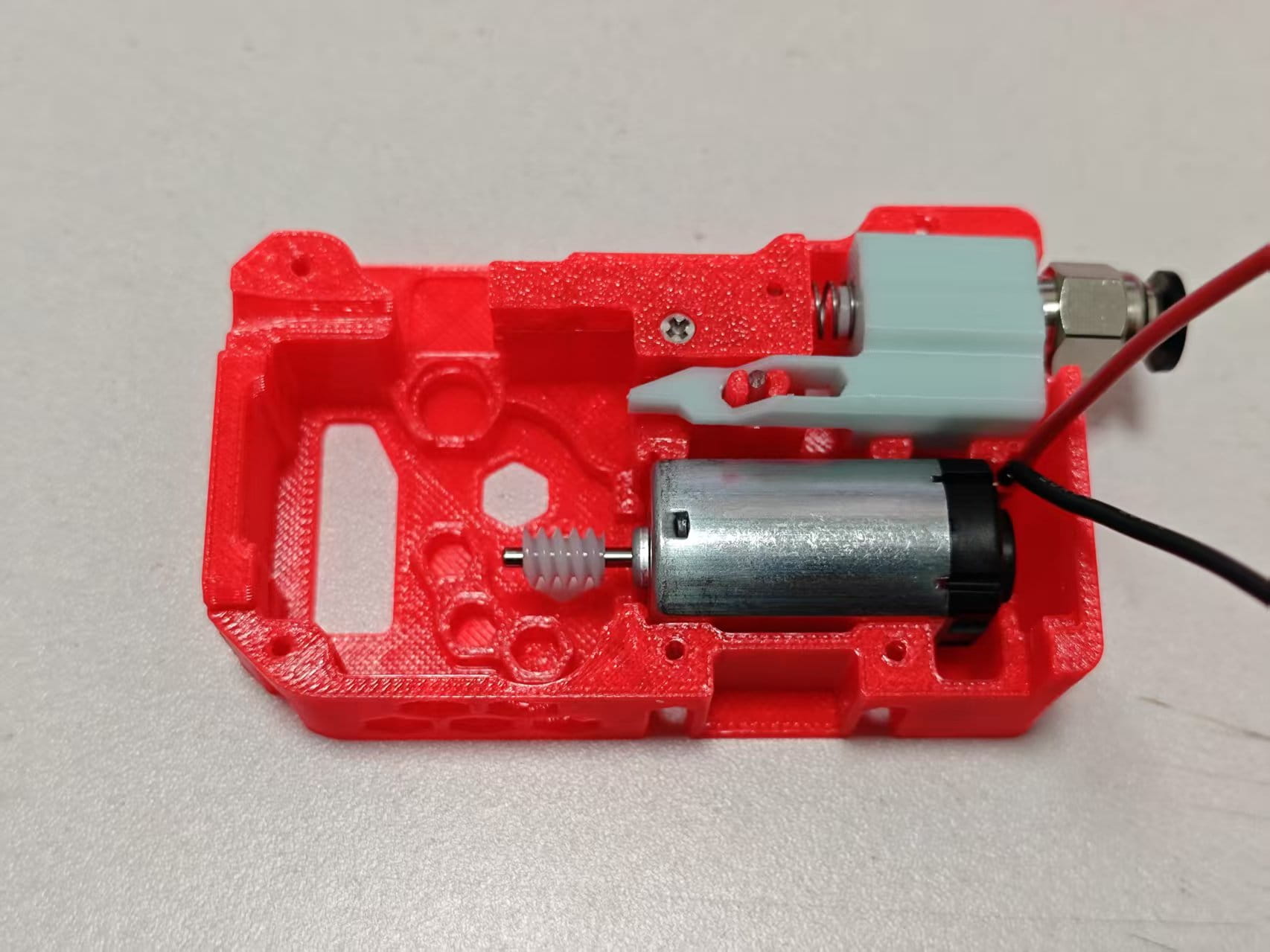
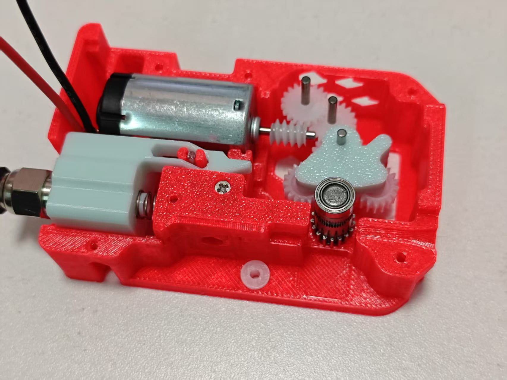
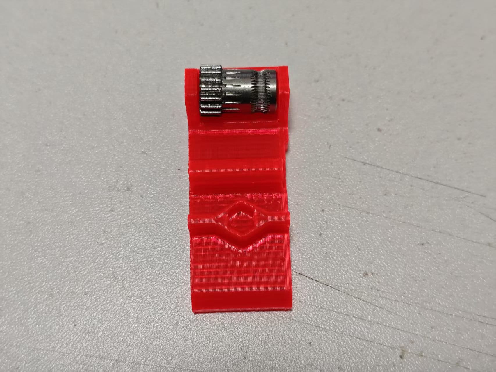
Place a 628 worm gear on the installation aid. Align the motor shaft with the worm gear hole and press down.
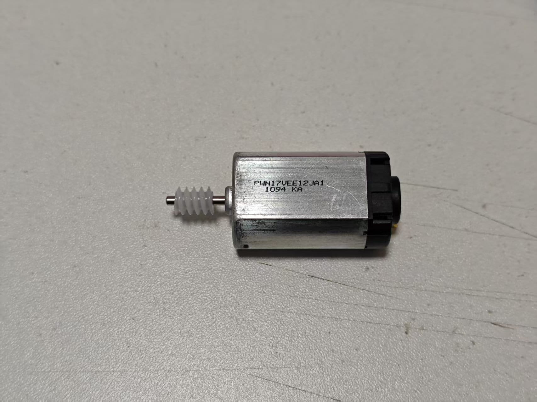
-
Solder 50mm wires to the motor. Pay attention to the direction.
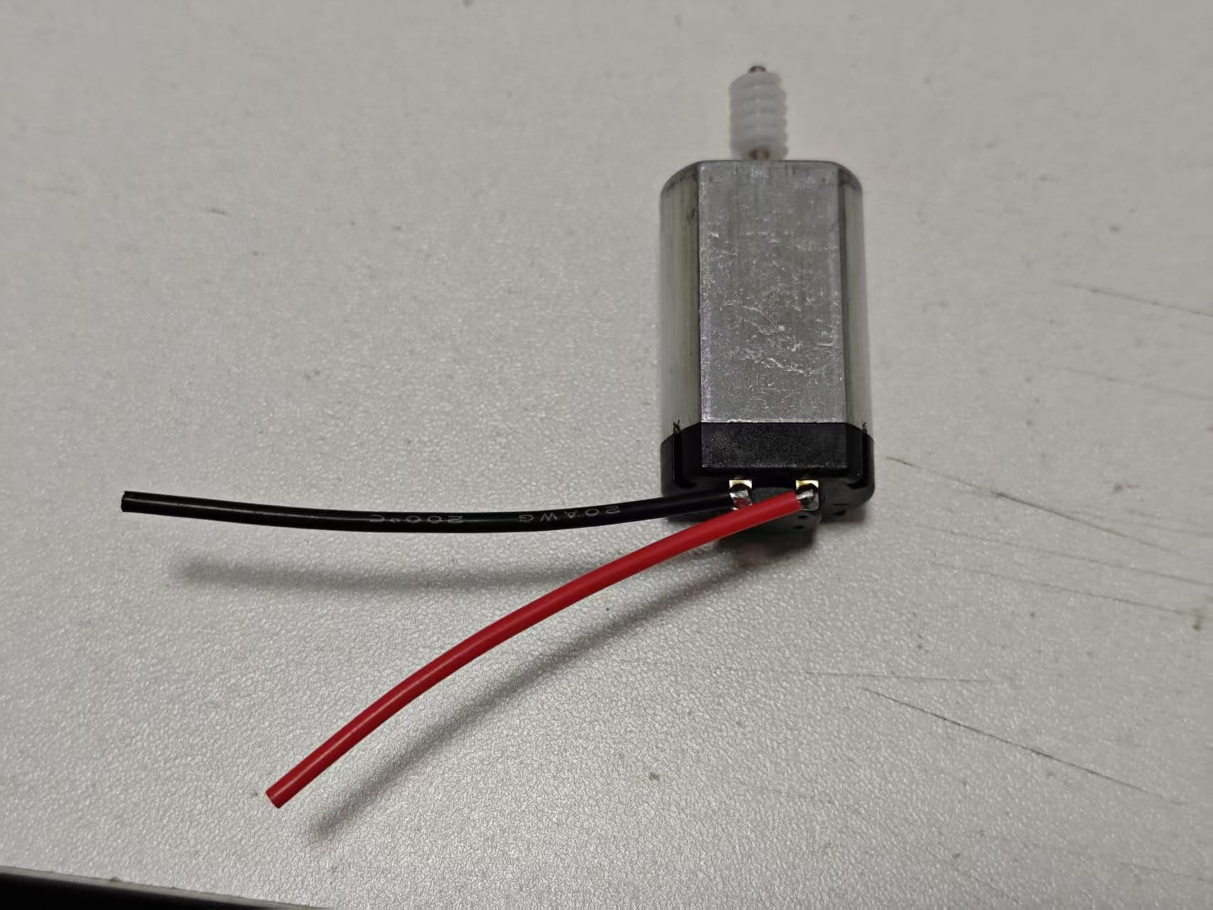
-
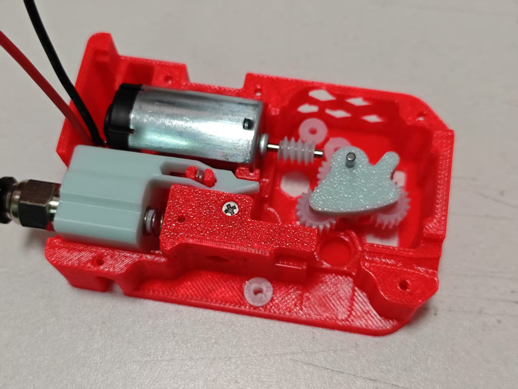
Mount the entire motor assembly onto the bottom cover.
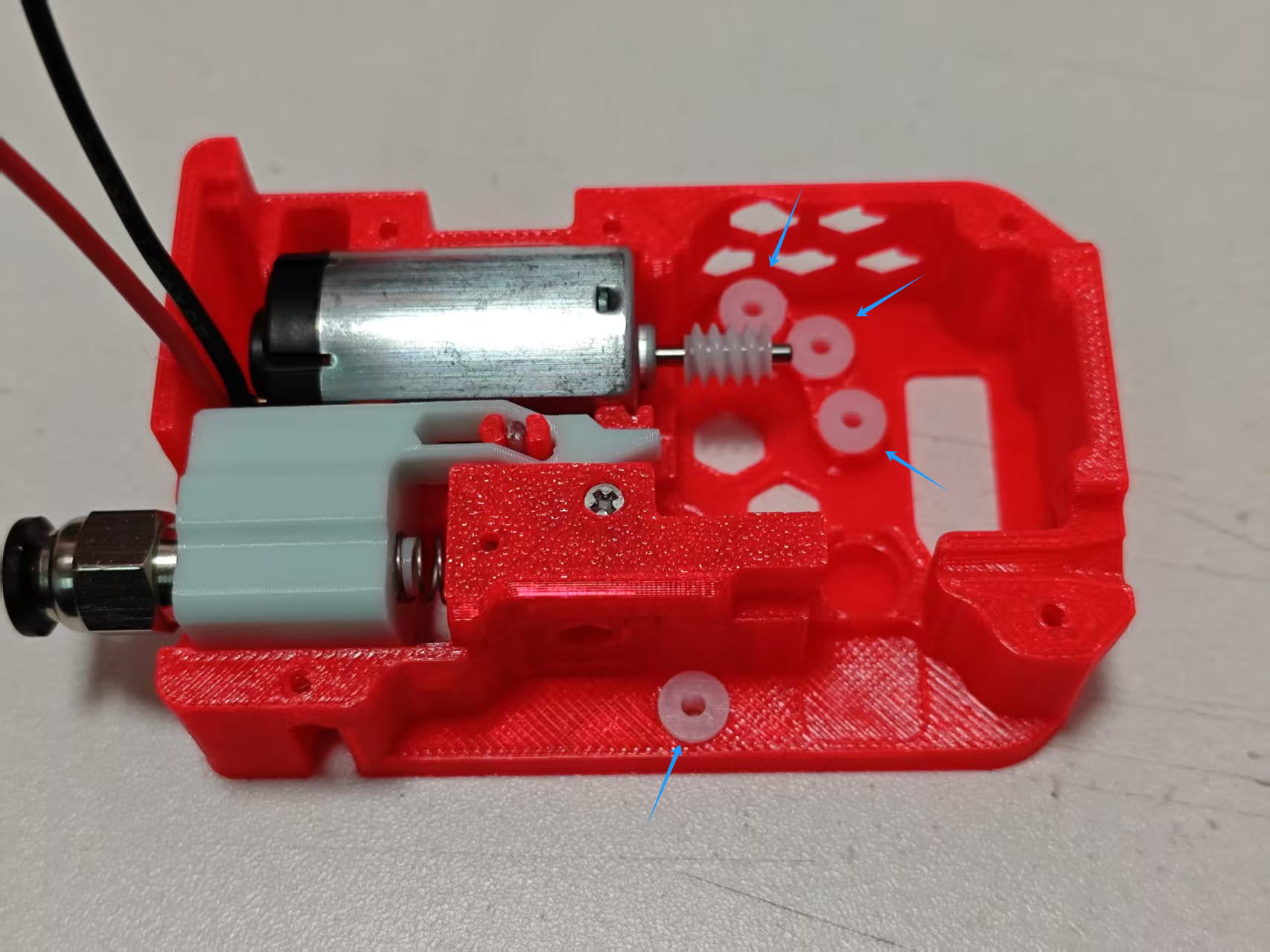
-
Install 4 x 62B bushings onto the bottom cover.
-
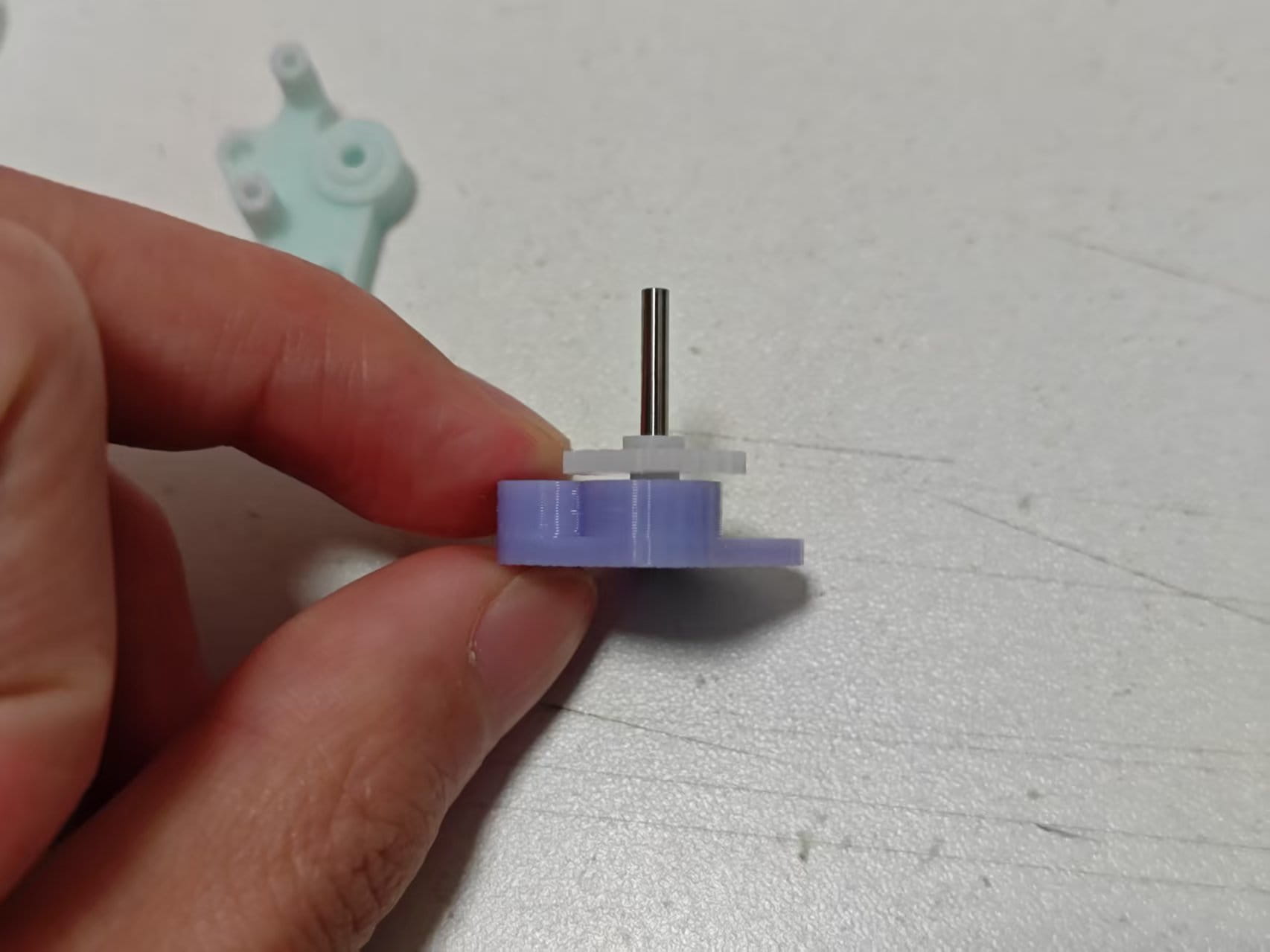
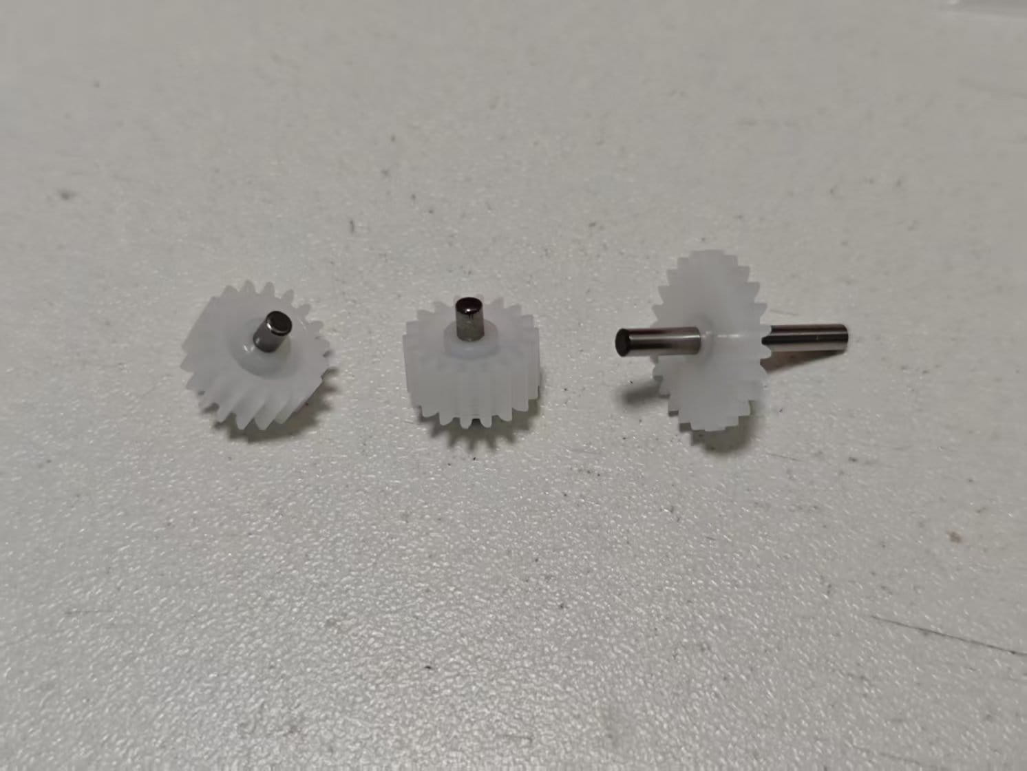
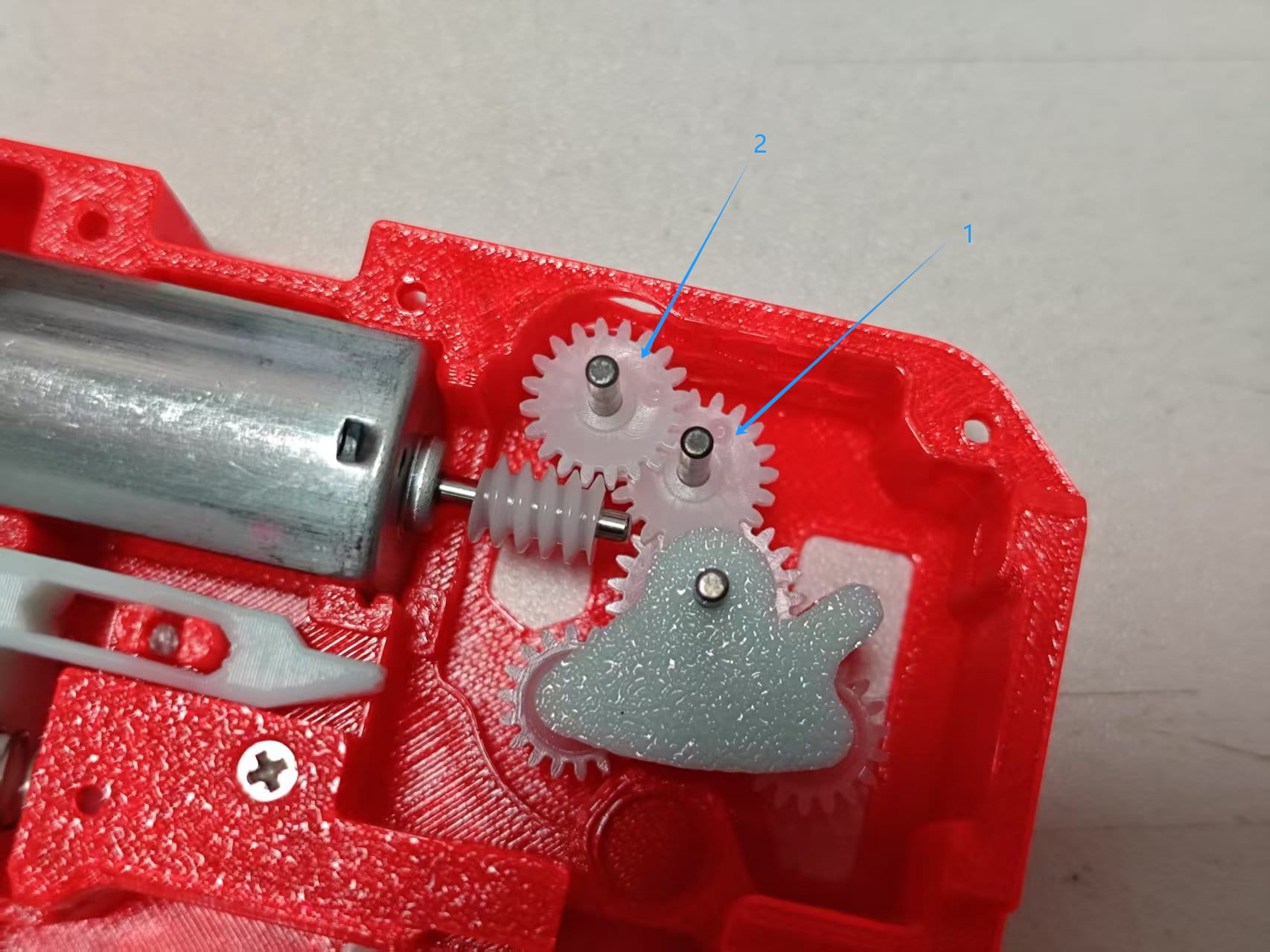
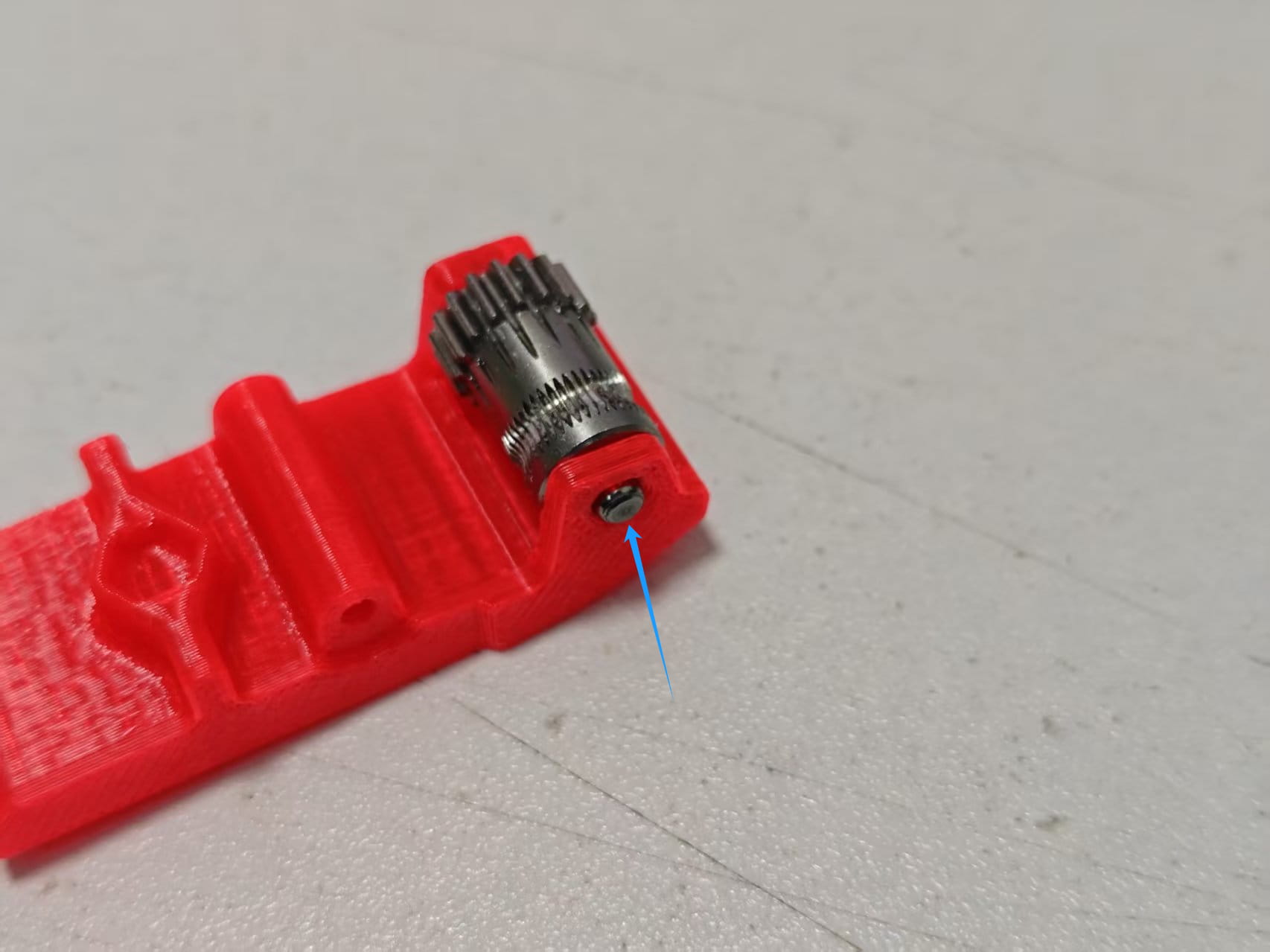
Assemble two 182A gears with two 2x6mm shafts. Position the gear in the center using the installation aid.
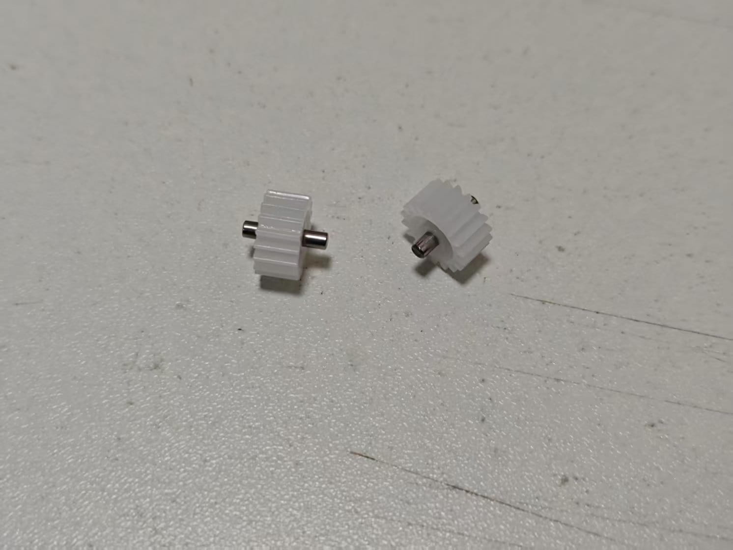
-
Assemble one 242A gear with a 2x20mm shaft. Use the installation aid to press in. The thinner step side should be about 6.1mm from the shaft end.
Gears ready:
-
Insert a 0.4x3x5mm spring into the side hole of Clutch Part B.
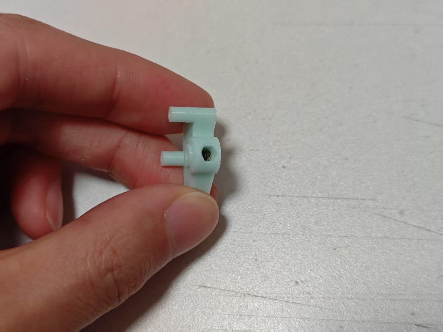
-
Press the spring with a 3mm tool (a 3mm SL screwdriver shown), then insert the 242A gear into Clutch Part B (larger step down).
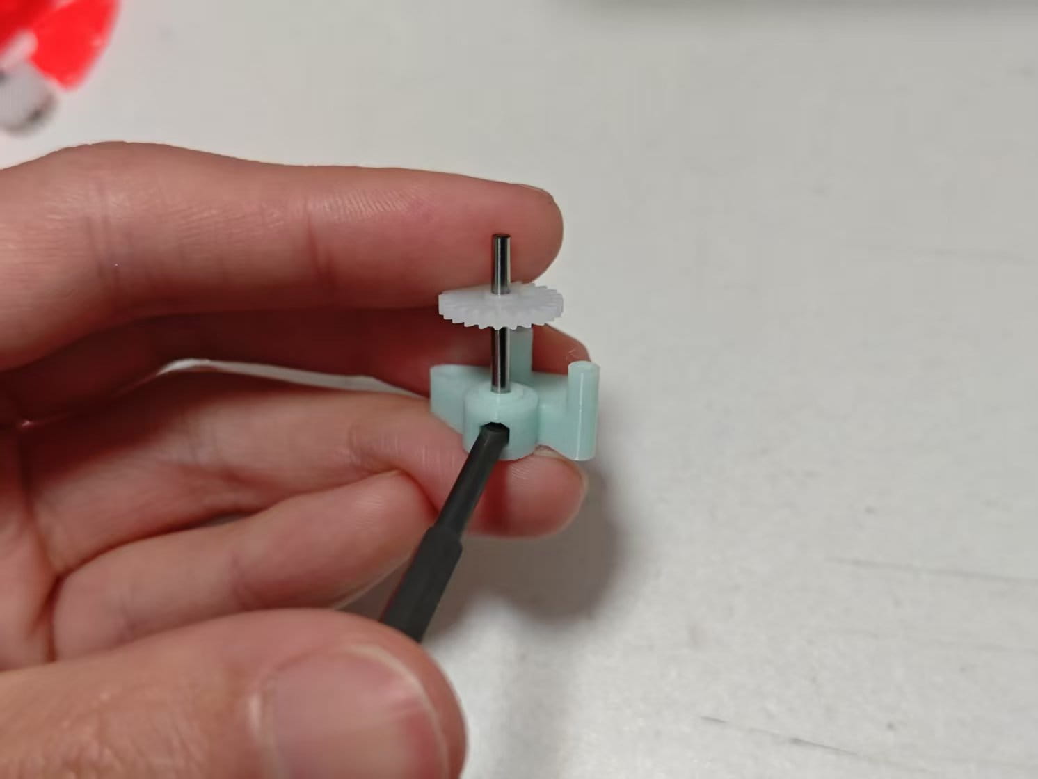
-
Insert two 182A gears into the other two holes of Clutch Part B. If not centered, insert the shorter side of the shaft.
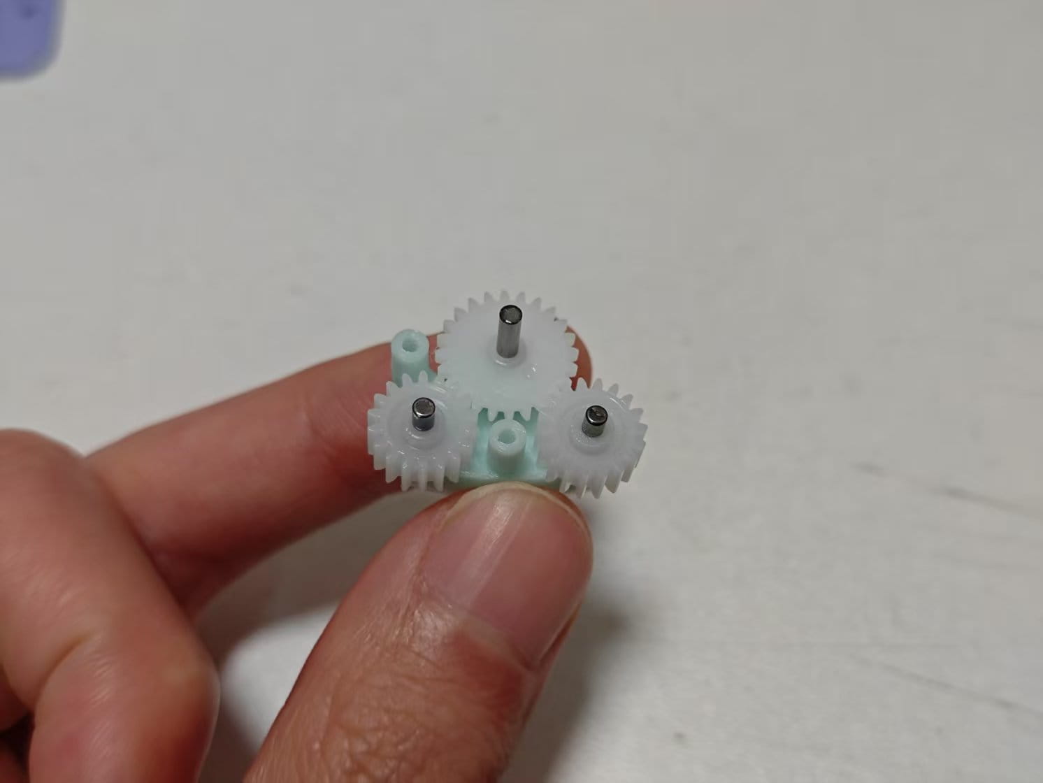
-
Place Clutch Part A and lock with two M2x8 screws. The clutch gears should rotate with spring resistance.
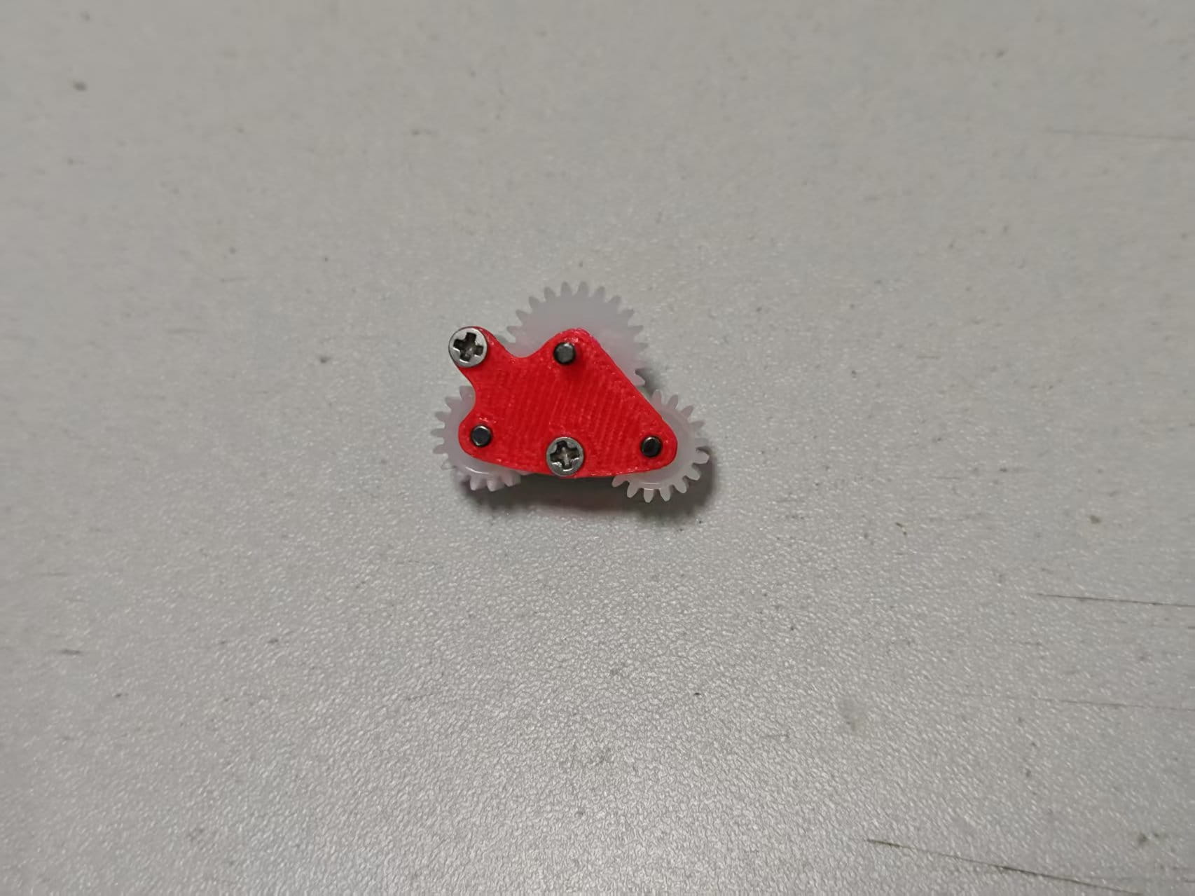
-
Insert the clutch assembly into the bottom cover.
-
Install two 20082B gears and insert a 2x20mm shaft.
-
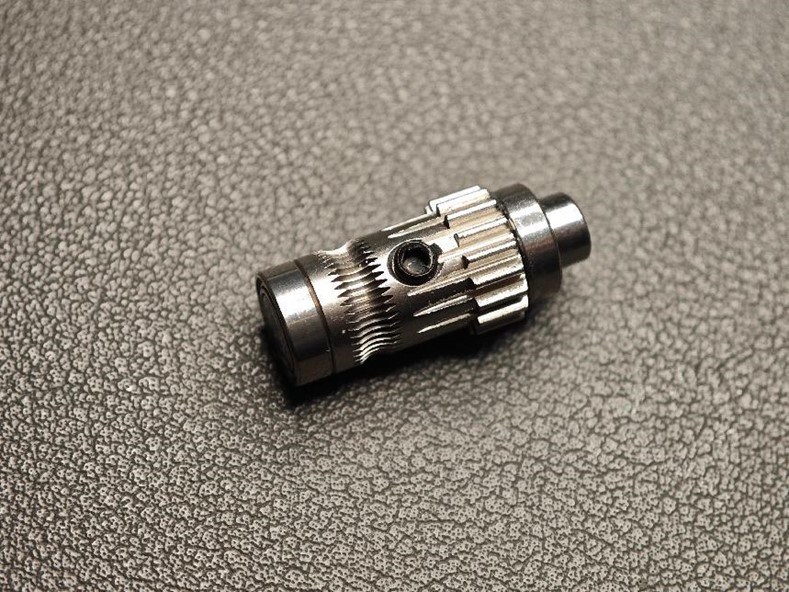
Assemble the extruder wheel from the BMG parts (screw hole type), two MR85 bearings, and a 5x22mm shaft.
A word of caution: please handle the combination of BMG gear set, D5*2 shaft and bearings with care, as the fit of the gears and shafts is sometimes very tight, and if it unfortunately gets stuck, it is very difficult to get it out again
- Gather the following parts:
- Extrusion wheel with screw hole !!!!!! IMPORTANT
- Black set screw
- One thick axle (5 × 22mm)
- Two bearings (MR85ZZ).
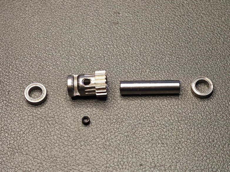
then Assemble the Extrusion Wheel
- Assemble as shown in the diagram, paying close attention to orientation.
- One end of the thick axle must be flush with the bearing (to allow a flat surface for the magnet).
- Don’t forget to install the black set screw.
-
Install the extruder wheel into the base and apply grease to all POM gears.
-
Install 4 x 62B bushings onto the middle frame.
-
Place the middle frame on the base, align all shafts with the bushings.
-
Flip the assembly and lock all 5 holes with M2x8 screws.
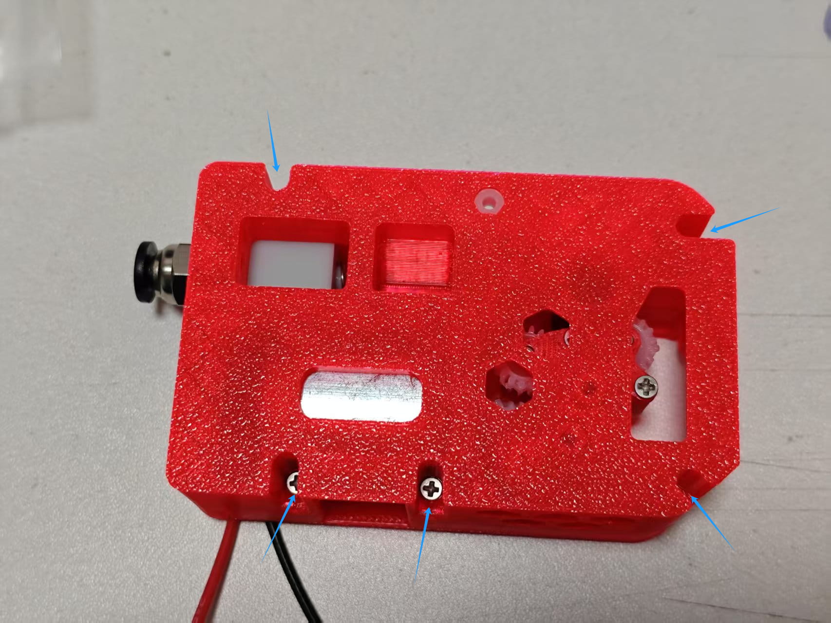
-
Flip back and install the magnet. The magnet should rotate with the extruder wheel.
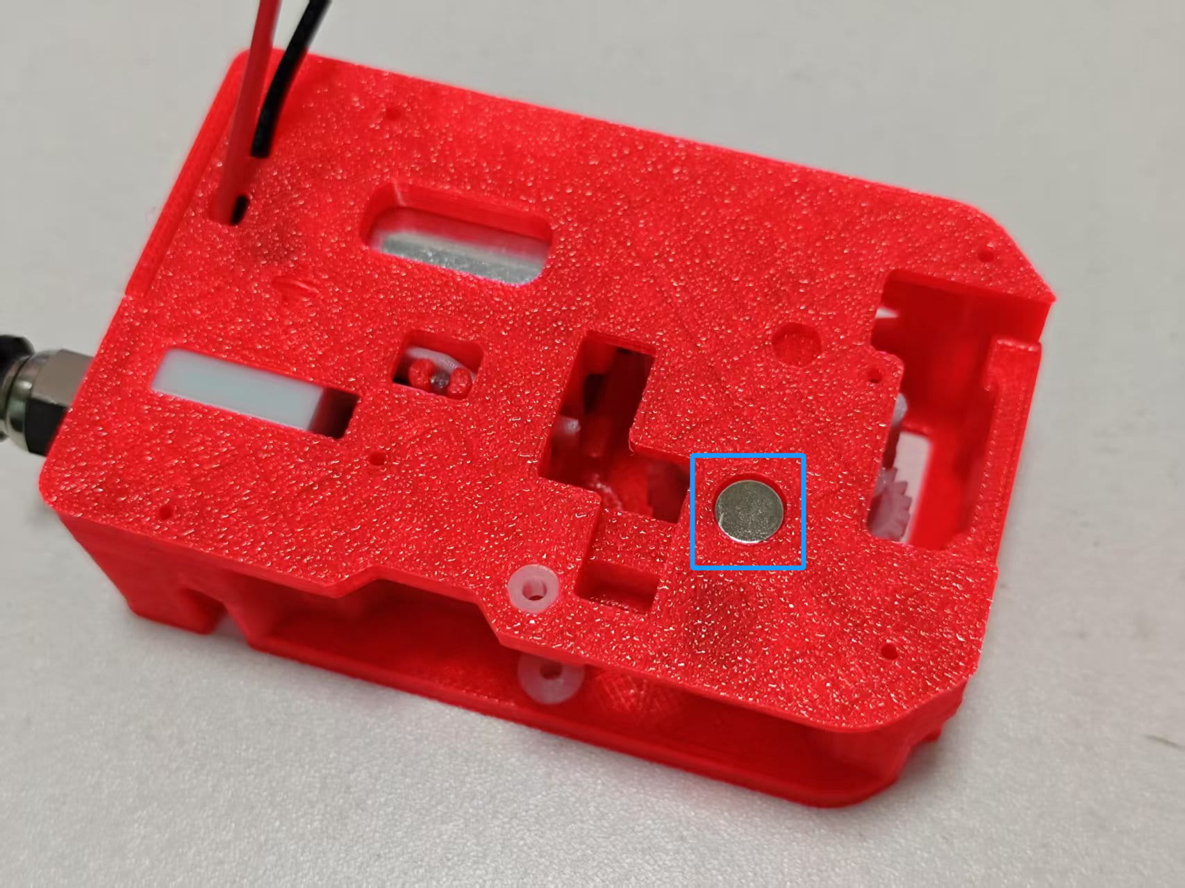
-
Place the PCB onto the middle frame and lock with M2x8 screws.
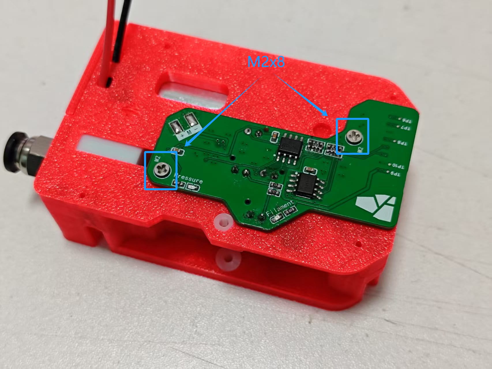
-
Trim the motor wires and solder them onto the PCB.
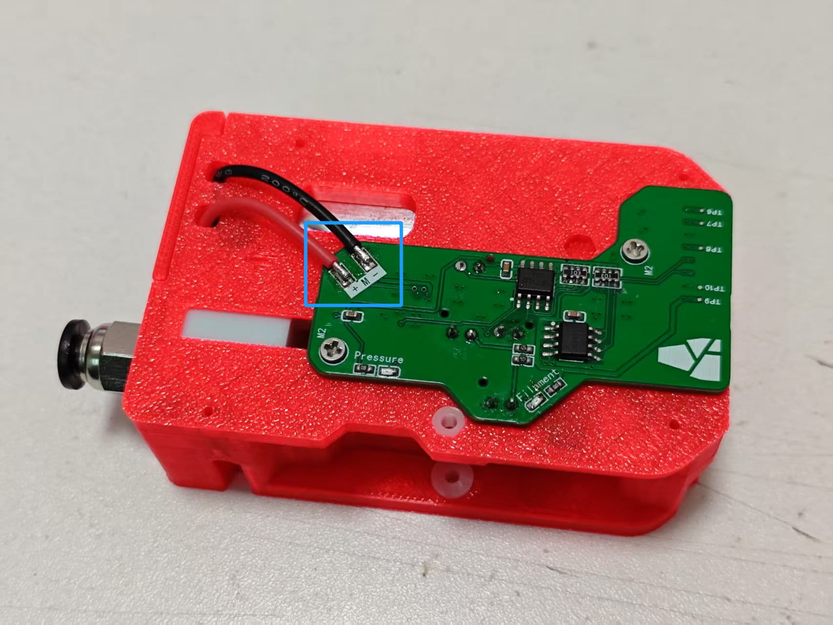
-
Insert two needle bearings into the extruder wheel without screw holes from the BMG kit. Install into the handle, minding the direction.
-
Insert the shaft into the handle. After installation, the extruder wheel should spin smoothly.
-
Mount the handle onto the assembly. Place a 0.5x6x10mm spring into the middle spring hole.
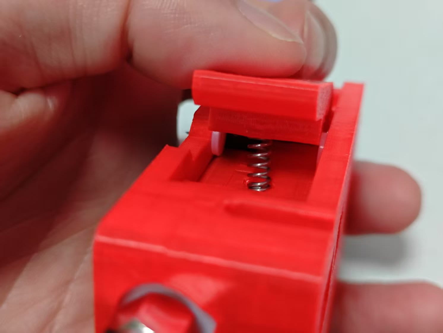
-
Press the handle and insert a 2x6mm shaft from the right side.
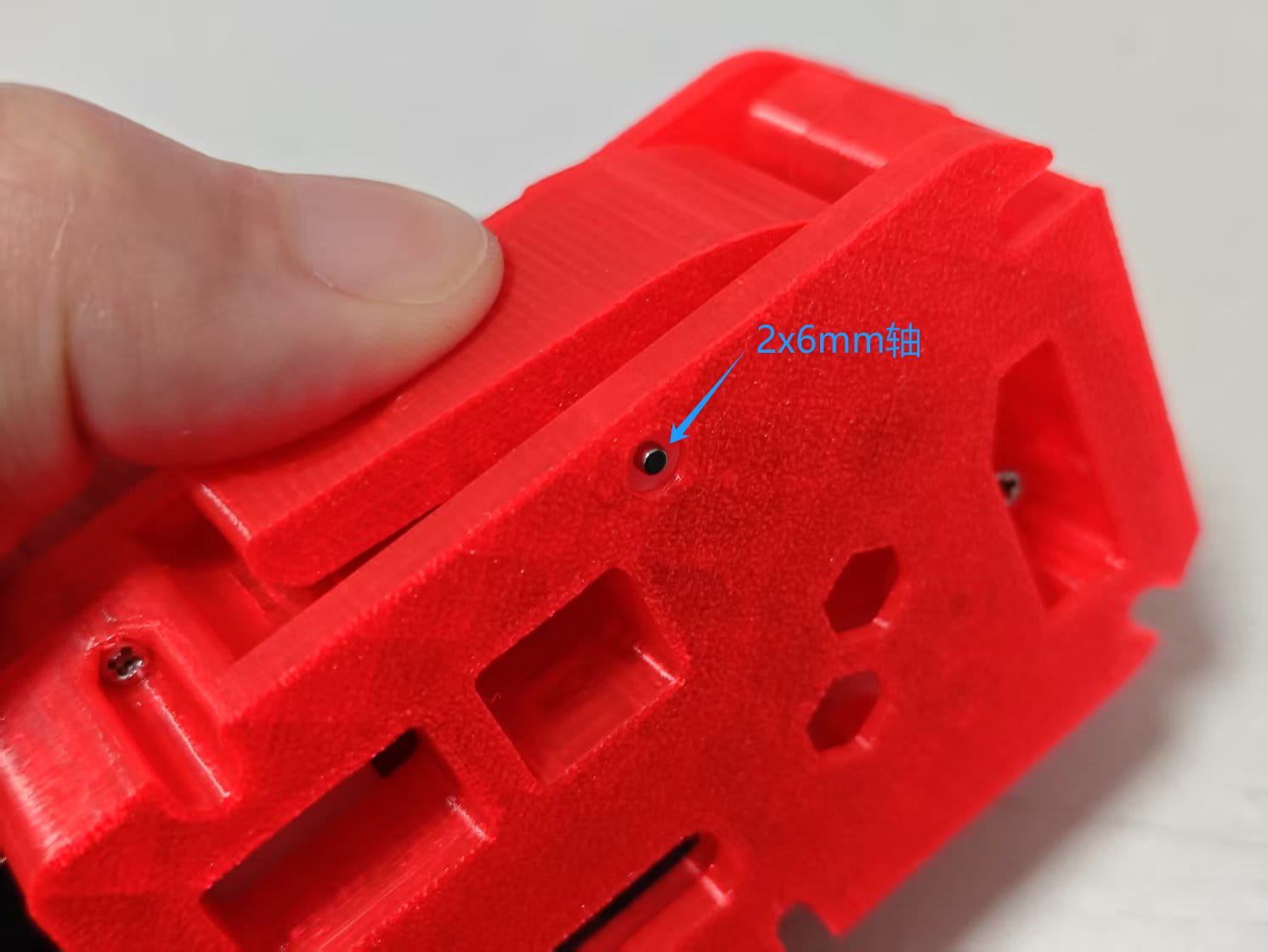
-
Hold the handle and insert a 2x20mm shaft from the other side until fully seated.
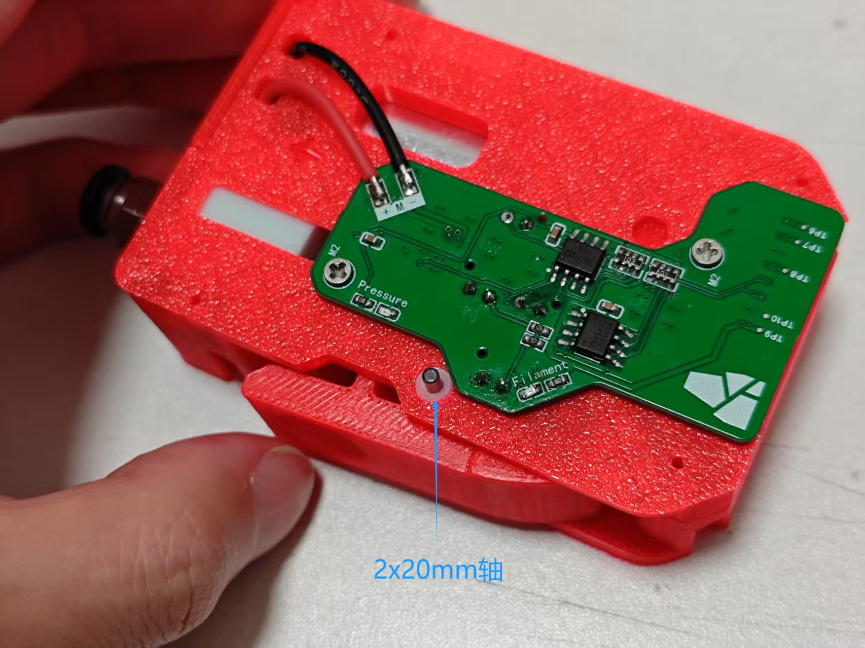
-
Finally, install the back cover and lock all 4 M2x8 screws. One module is complete.
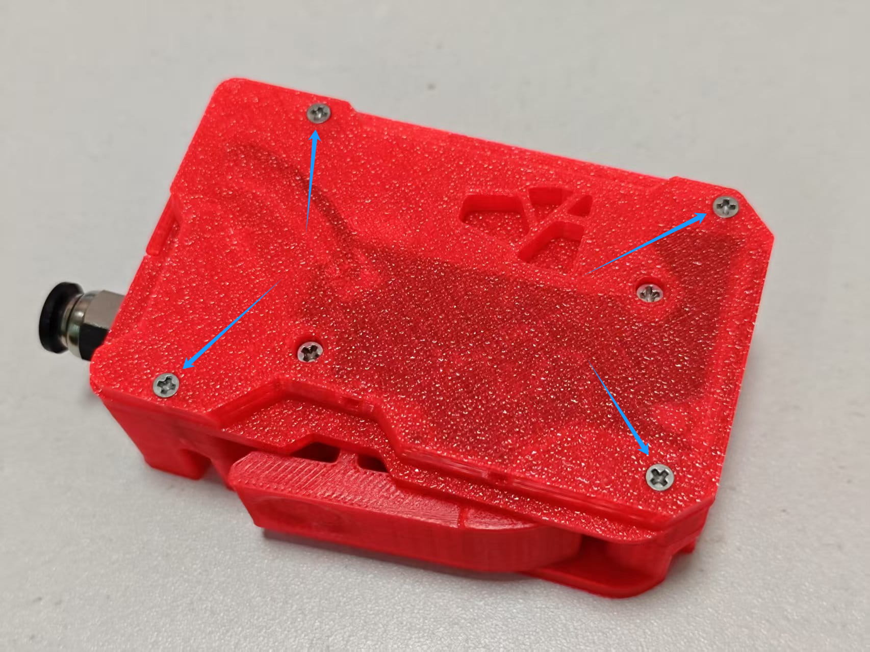
-
Repeat the same steps for the other three modules. After completion, refer to the 130 guide to test the modules.