¶ 370 Steel Ball Version Assembly Guide
This tutorial is made by @丸子
There's also an AMAZING video adapted to this release, made by @Lukas, link to youtube
¶ Introduction
This guide covers the assembly of the 3-14 version of the 370 Steel Ball model. It is also generally applicable to other steel ball versions.
¶ Preparation Before Assembly
You will need a fully soldered BMCU circuit board. Please ensure there are no soldering defects such as cold joints, missed spots, solder bridges, or incorrect connections.
The firmware must be flashed before assembly. For the flashing guide, please refer to the group files.
Use firmware version 3-14, which supports both A series and P series.
✅ Model used in this guide:
https://makerworld.com/zh/models/1250311-bmcu-370-steel-ball-version-v3-14#profileId-1272722
¶ Feeding Mechanism Assembly
¶ Component Overview
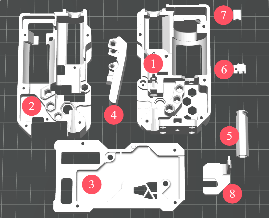
- ① Back Frame
- ② Middle Frame
- ③ Front Frame
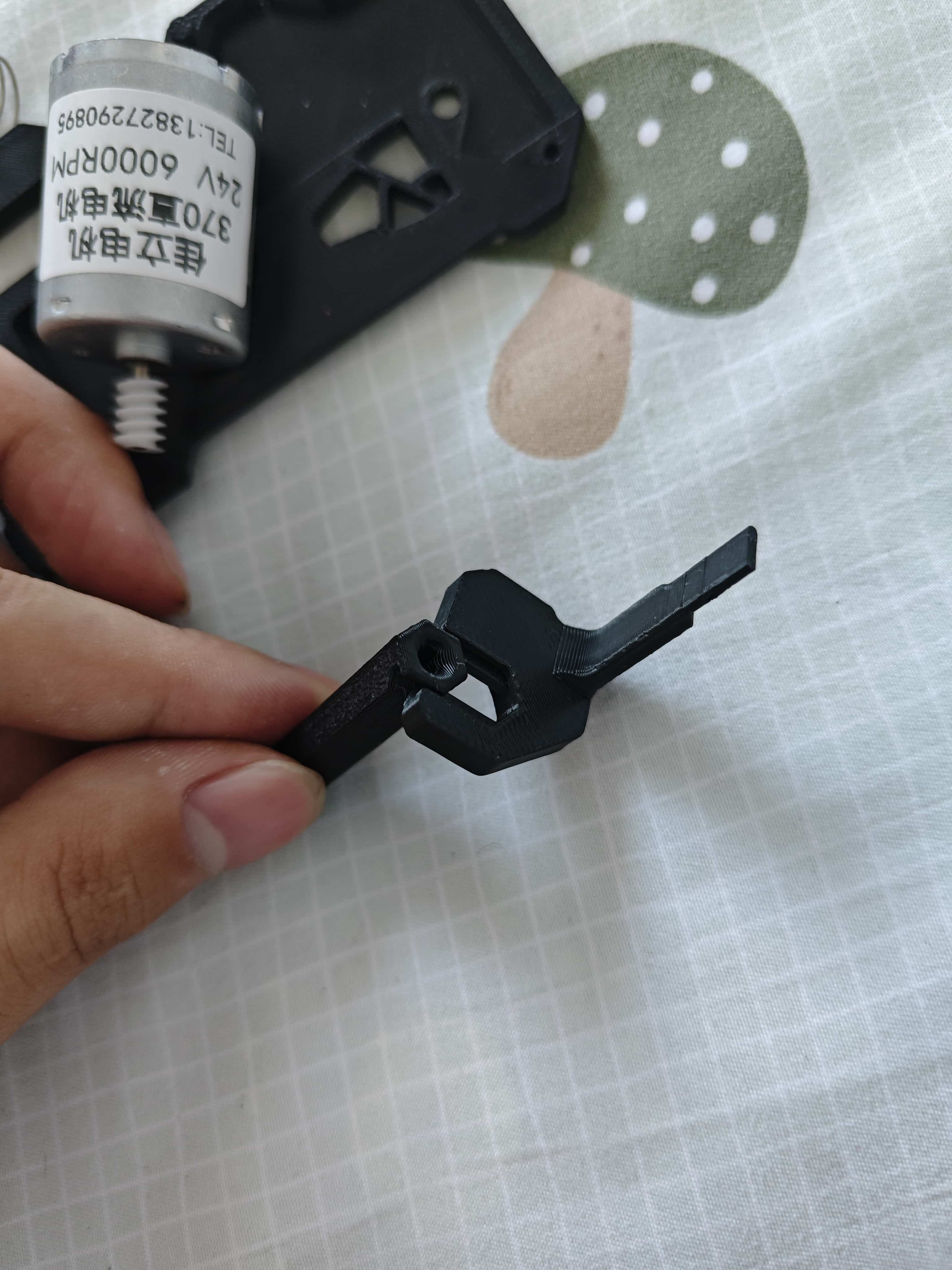
- ④ Lever
- ⑤ Buffer Slider Bar
- ⑥ Steel Ball Slider / Filament Break Sensor Slider
- ⑦ Nut block
- ⑧ Buffer slider
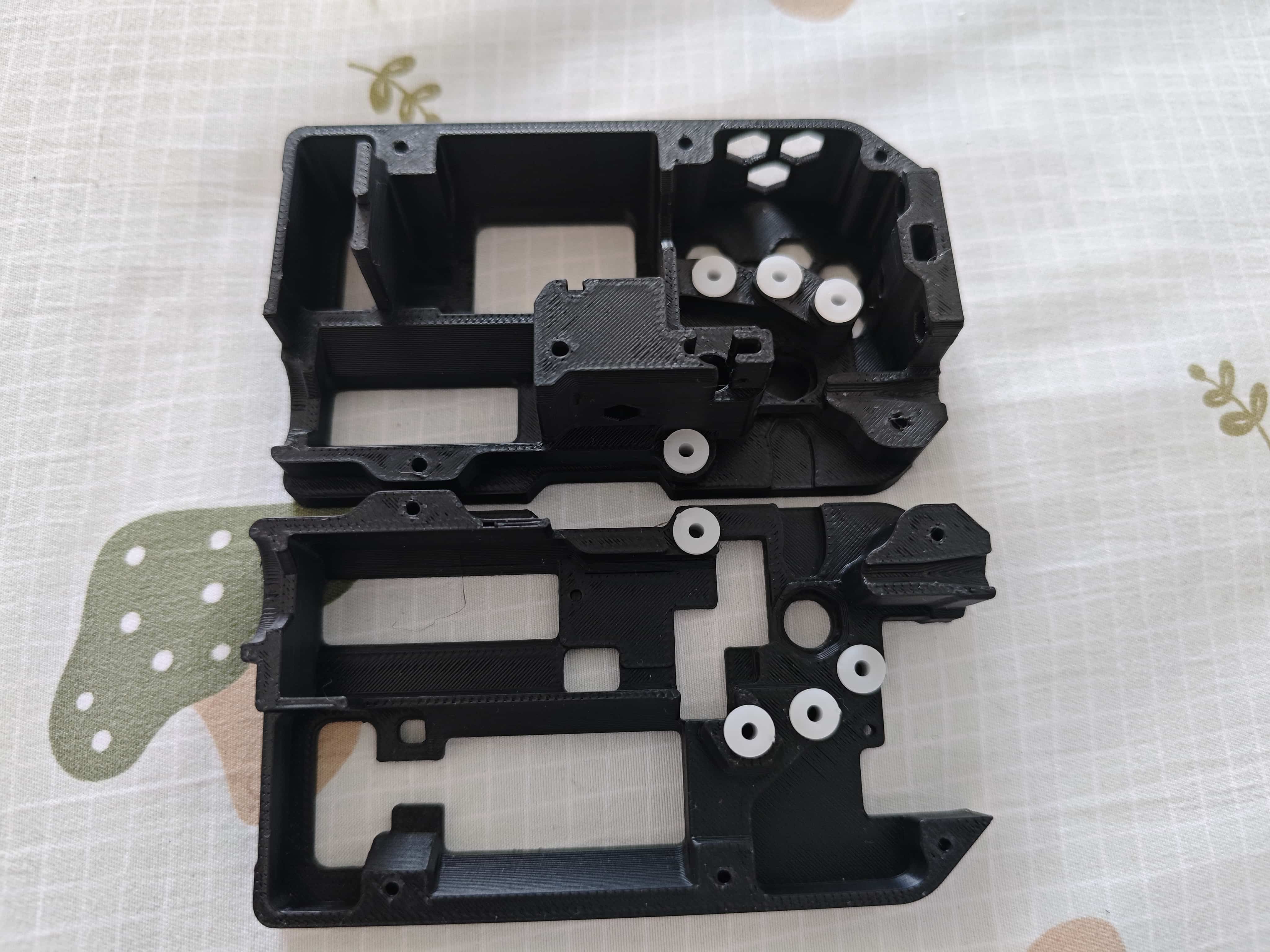
¶ Installing the Bushings
Insert the 62B bushings into the back cover and middle frame as shown below:
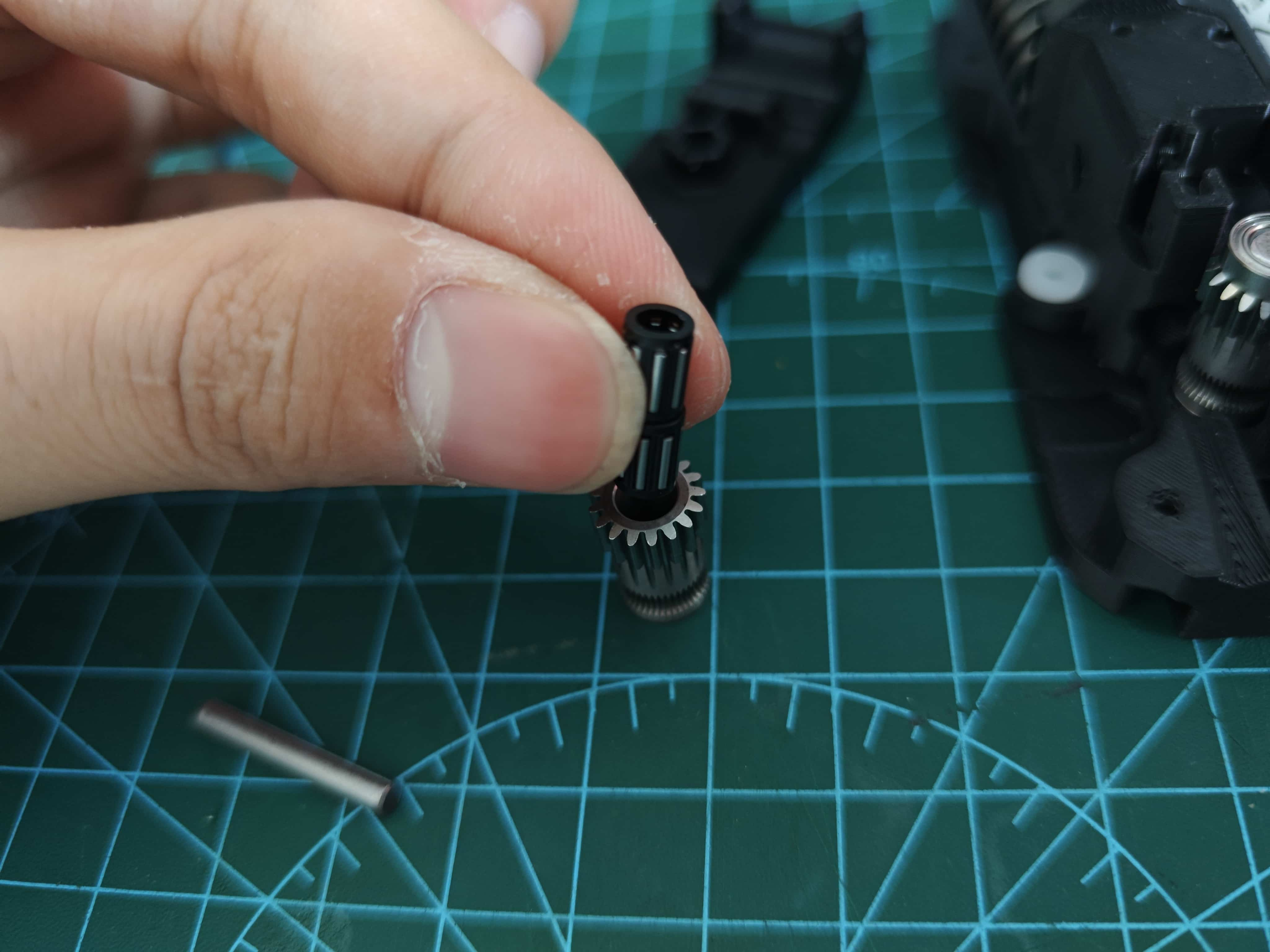
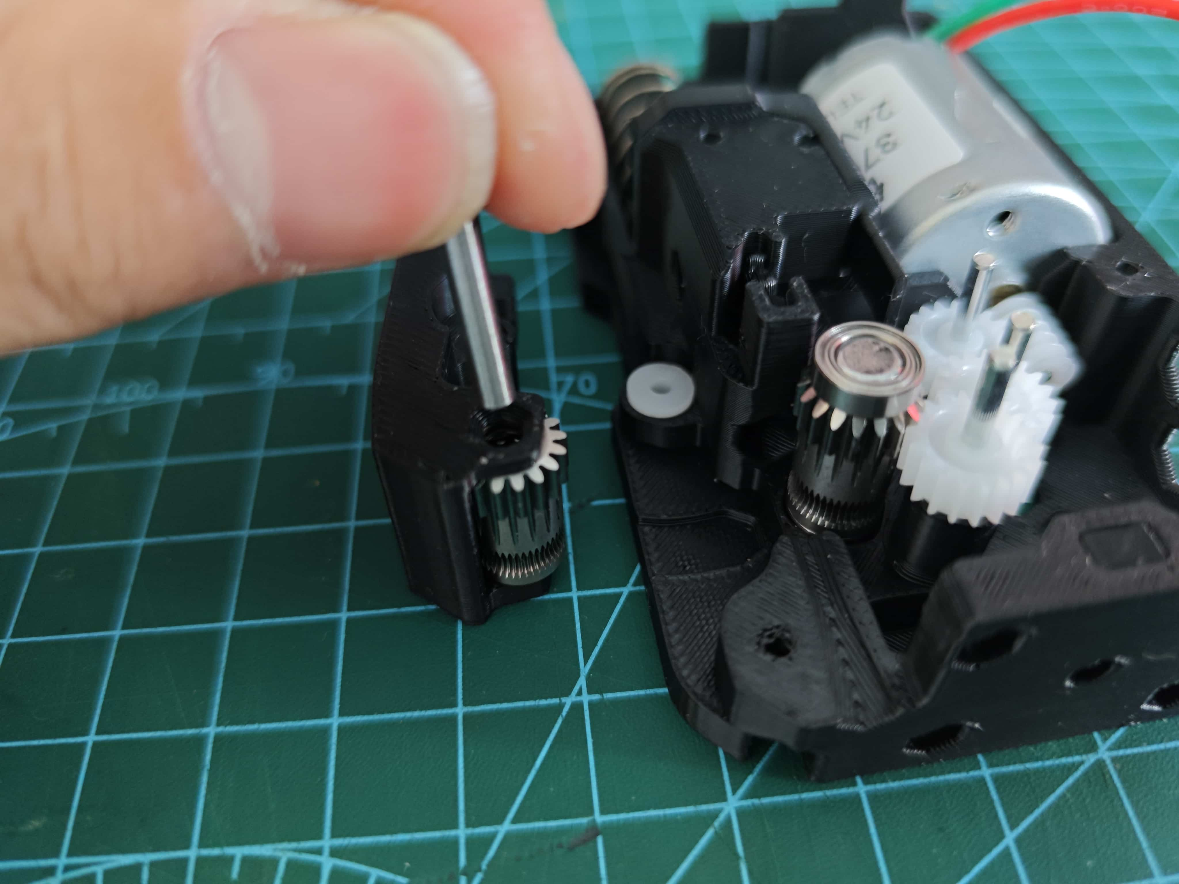
¶ Assembling the 182A Gear and 2x20 Shaft
Press the shaft into the gear as shown, ensuring equal lengths extend from both sides.

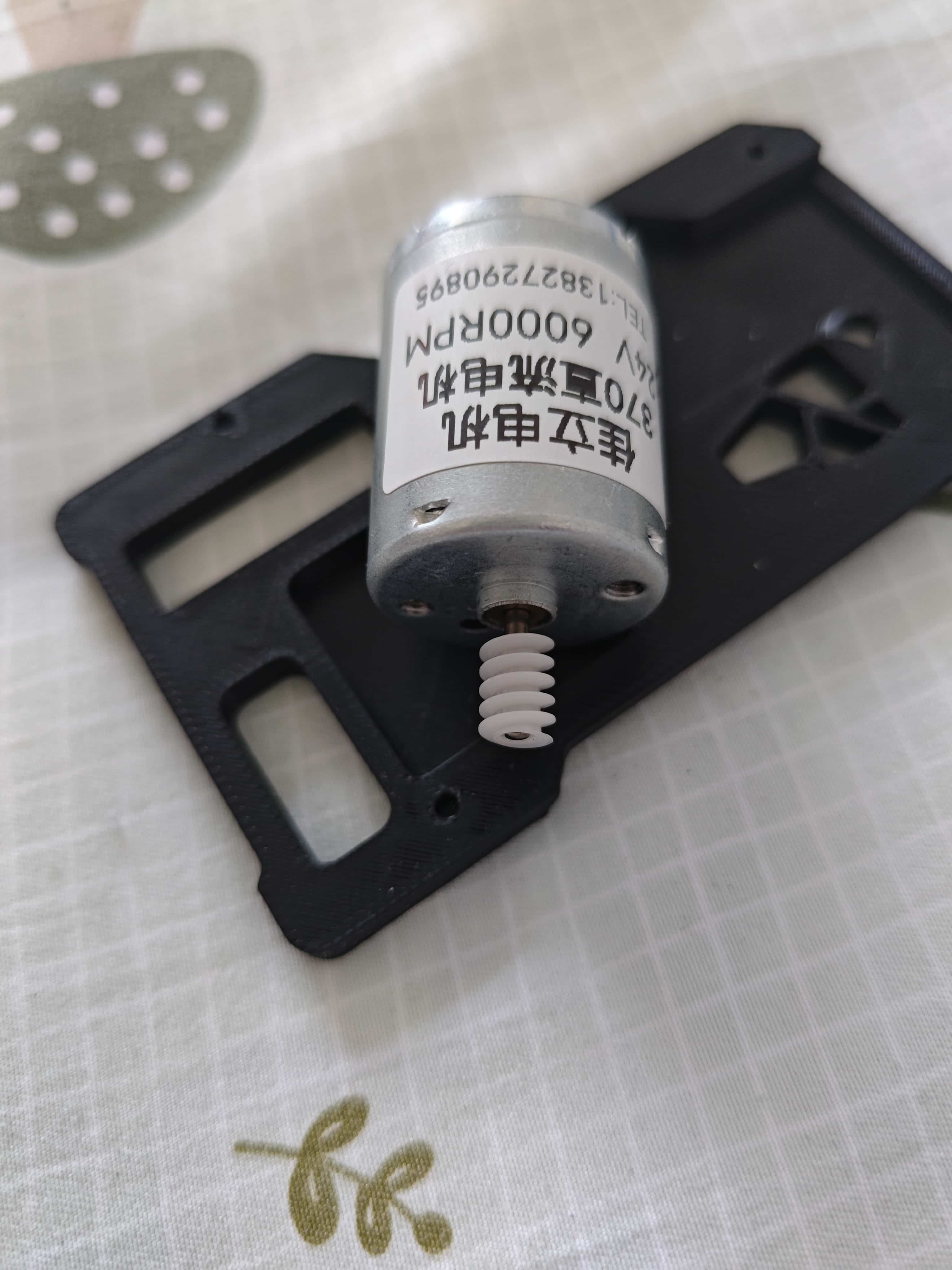
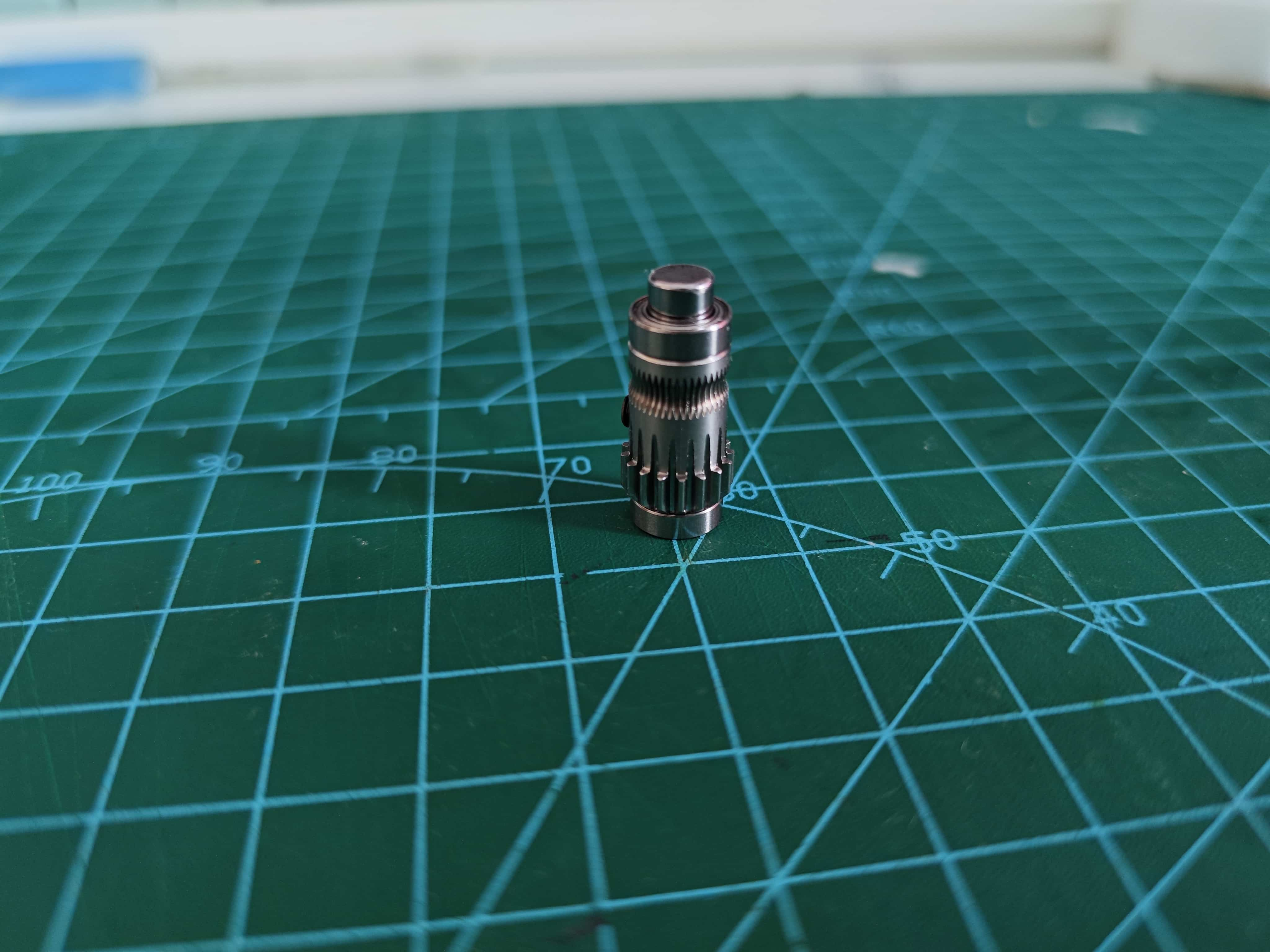
¶ Installing the Worm Gear on the 370 Motor
For Jiali motors, press the worm gear all the way down. The length should align perfectly.
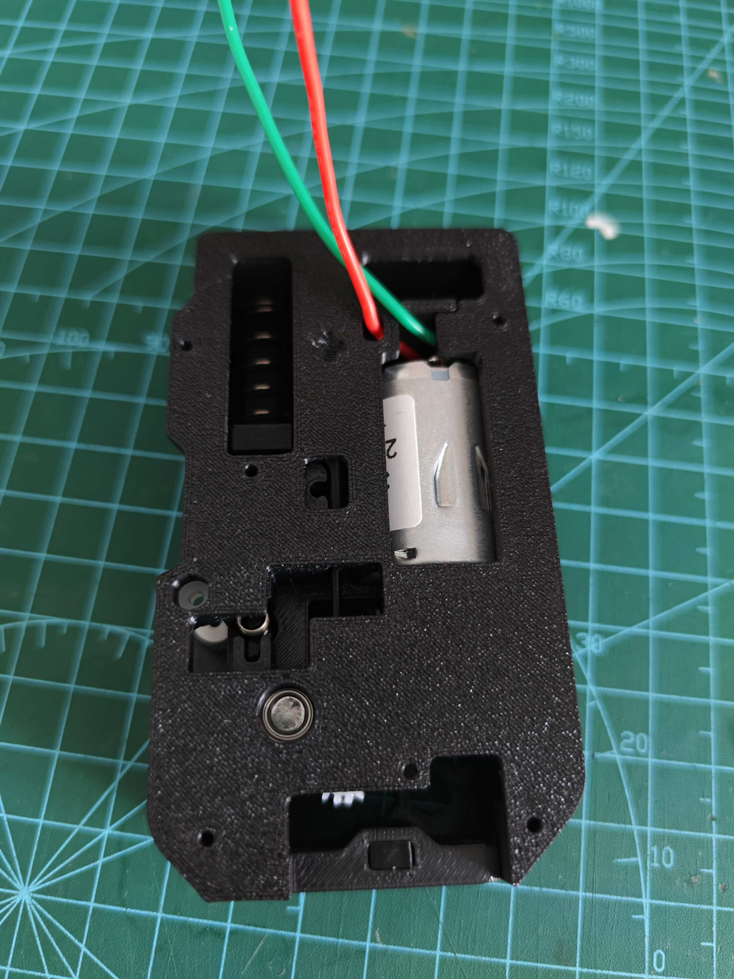
¶ Assembling the Buffer Unit
Combine the Buffer slider and the Slider bar.
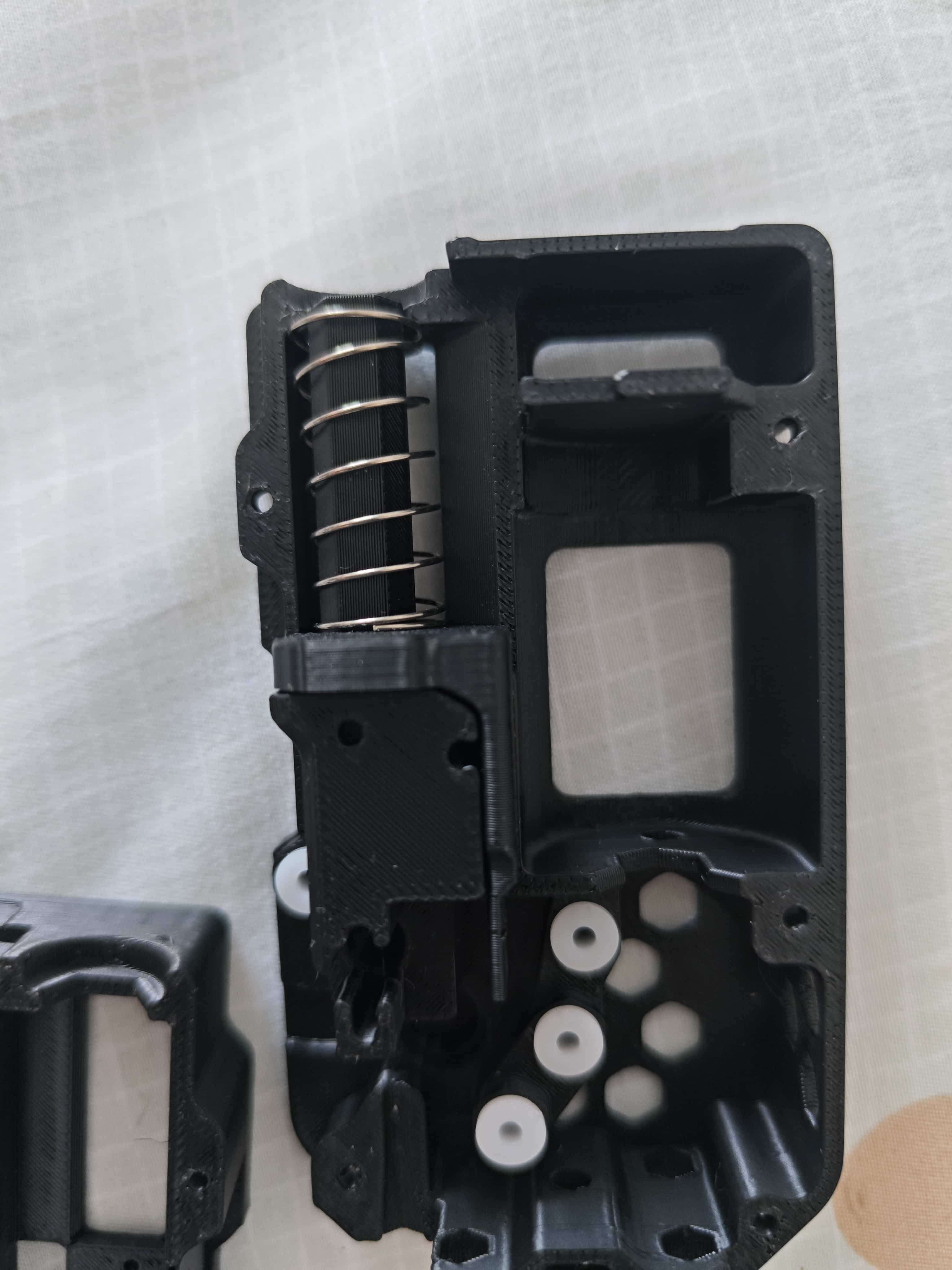
Slide the 0.6*12x30mm spring over the buffer unit and place it into the back cover.
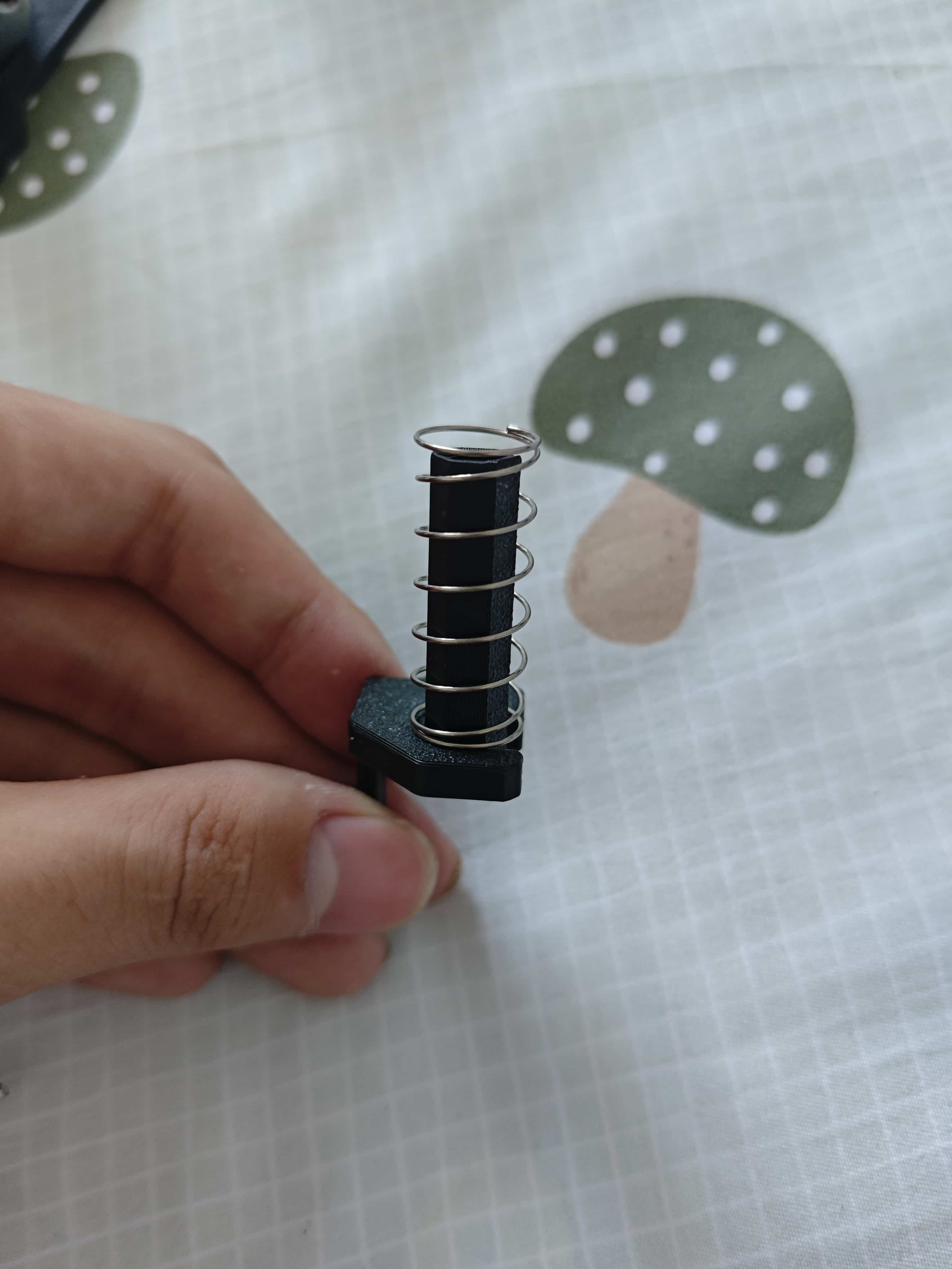
Ensure the spring hooks onto the edge of the back cover.
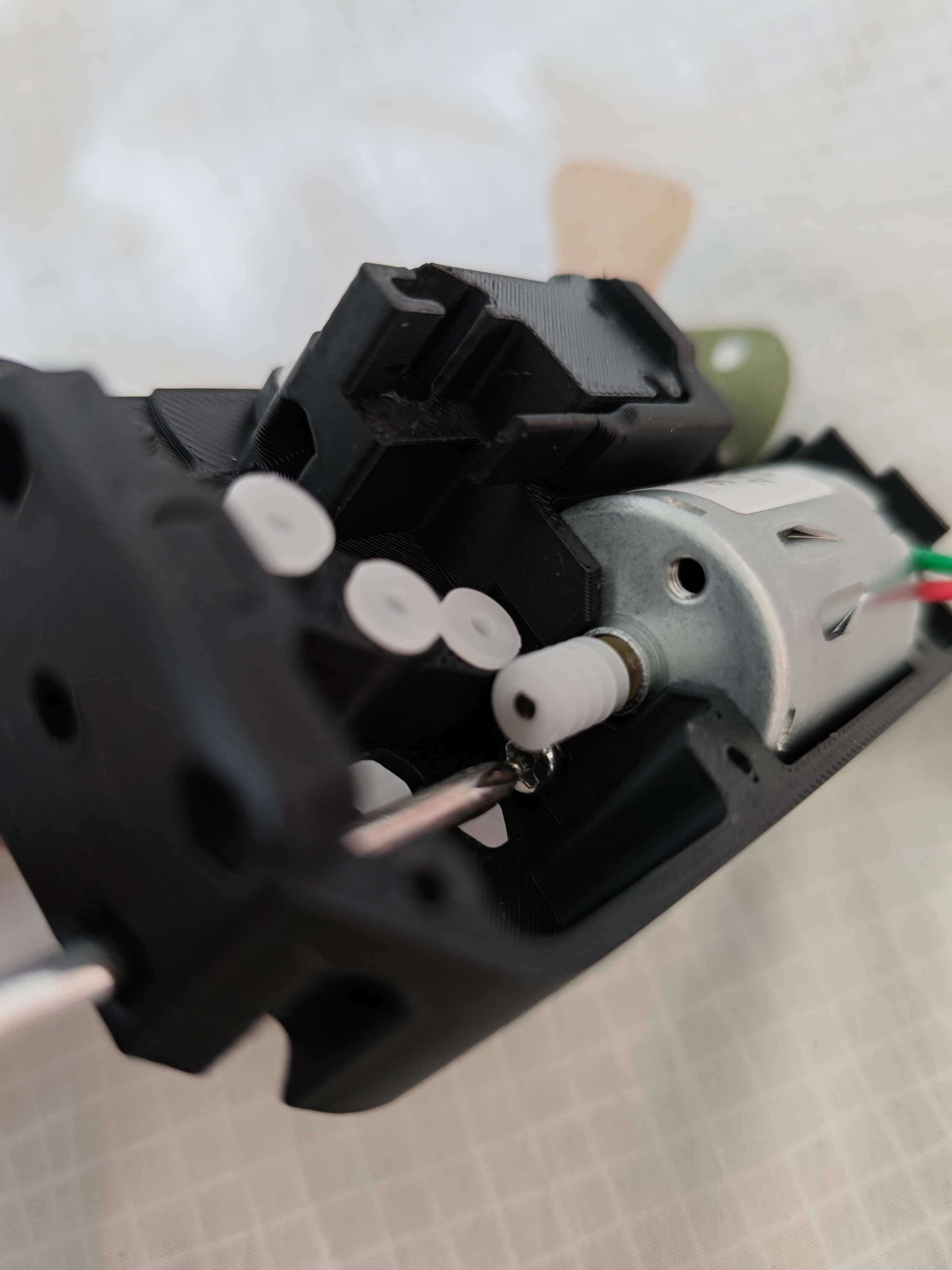
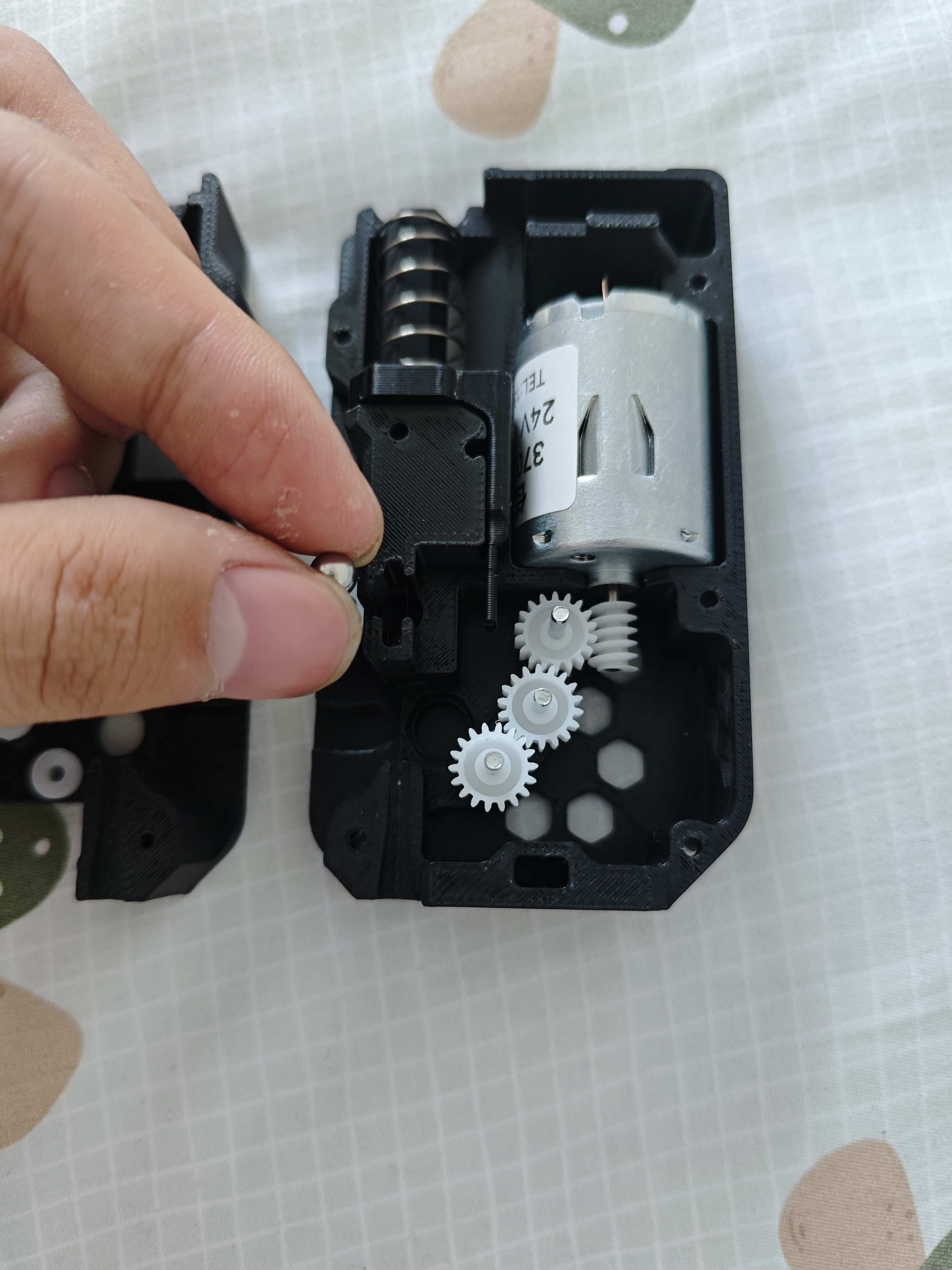
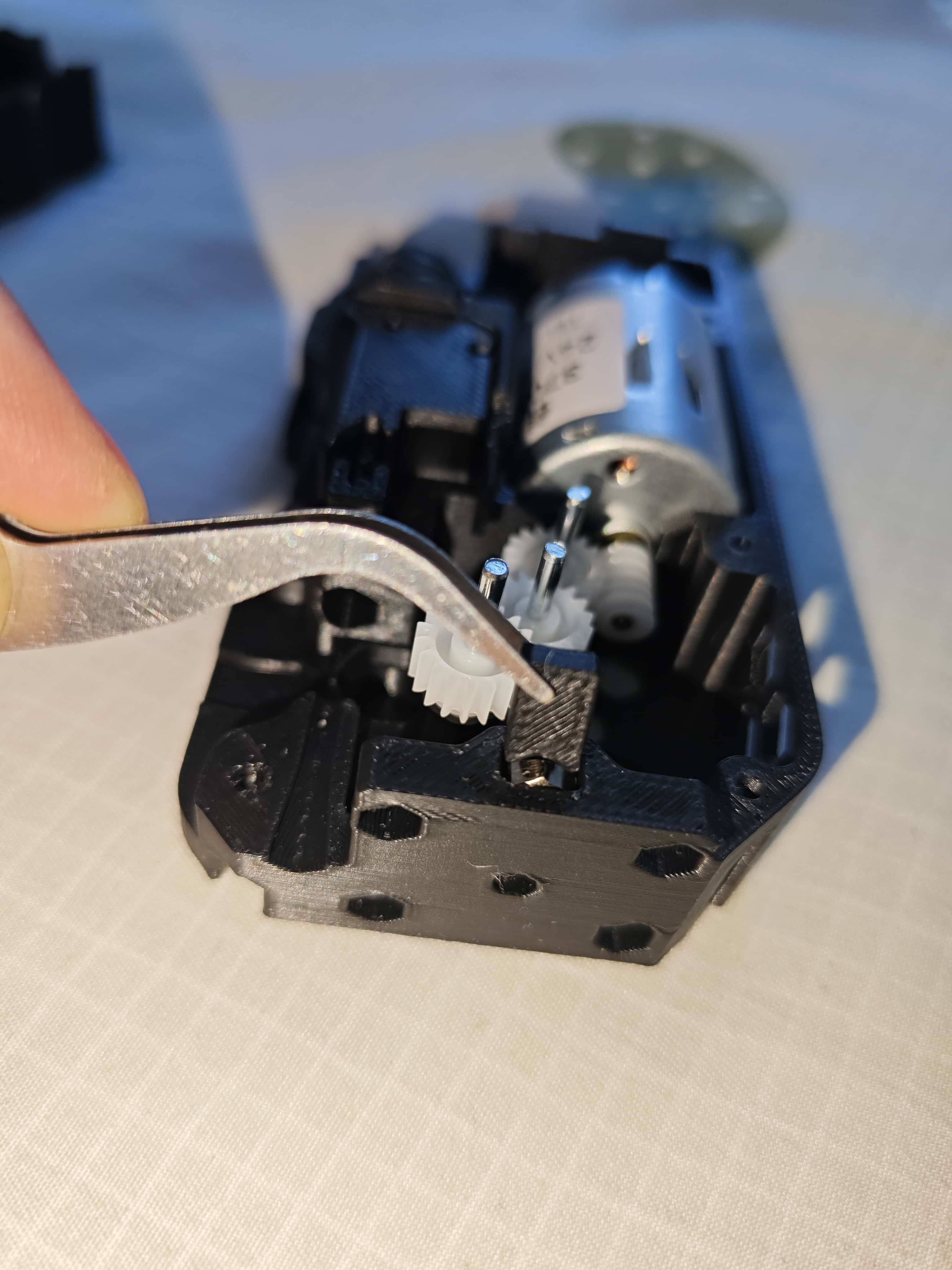
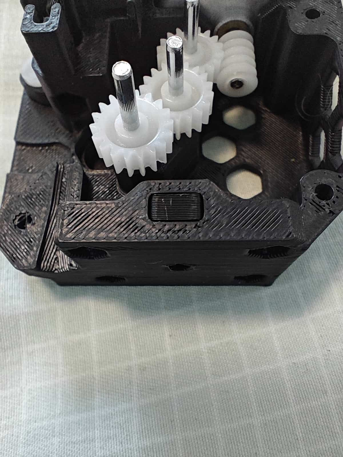
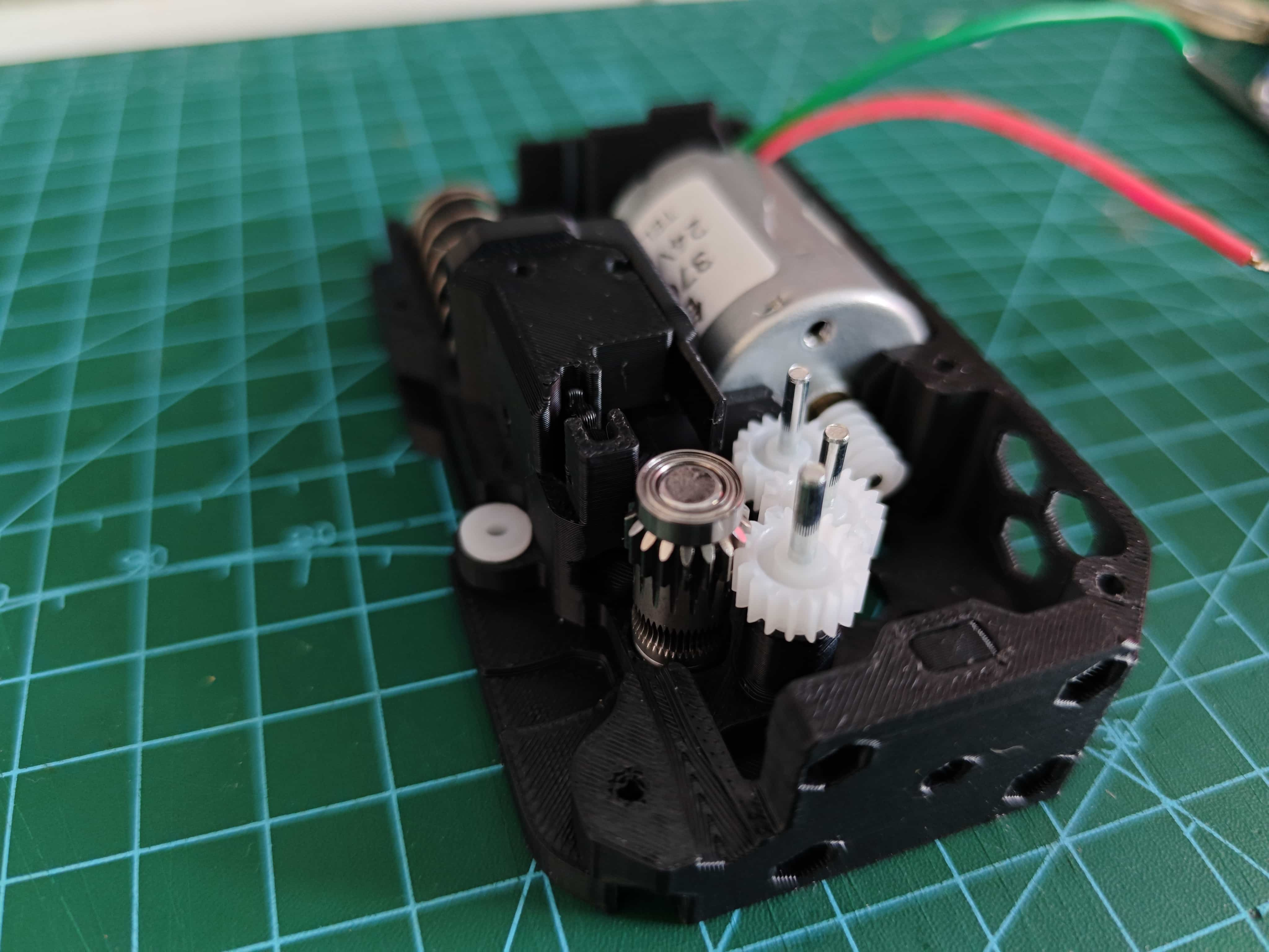
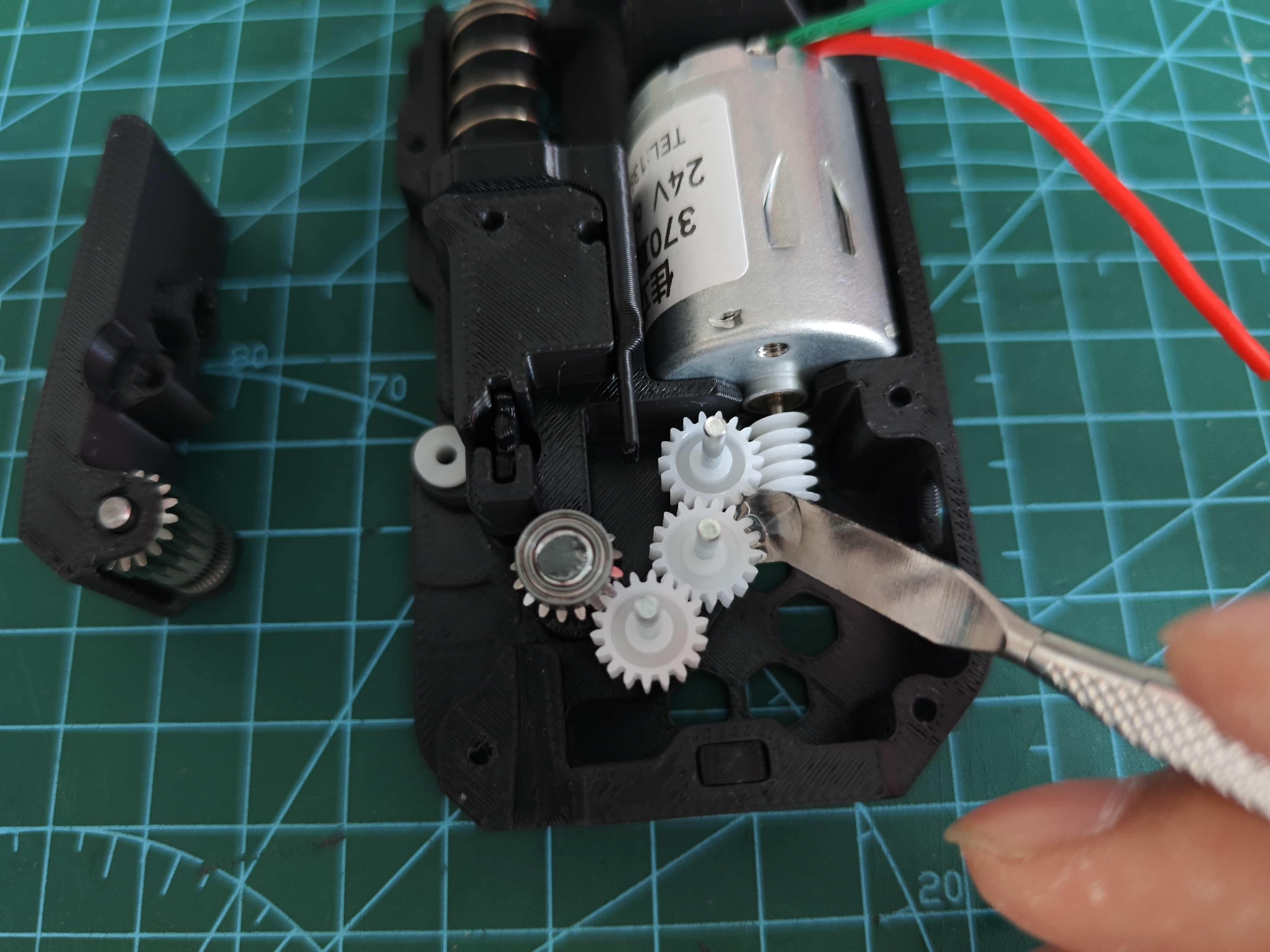
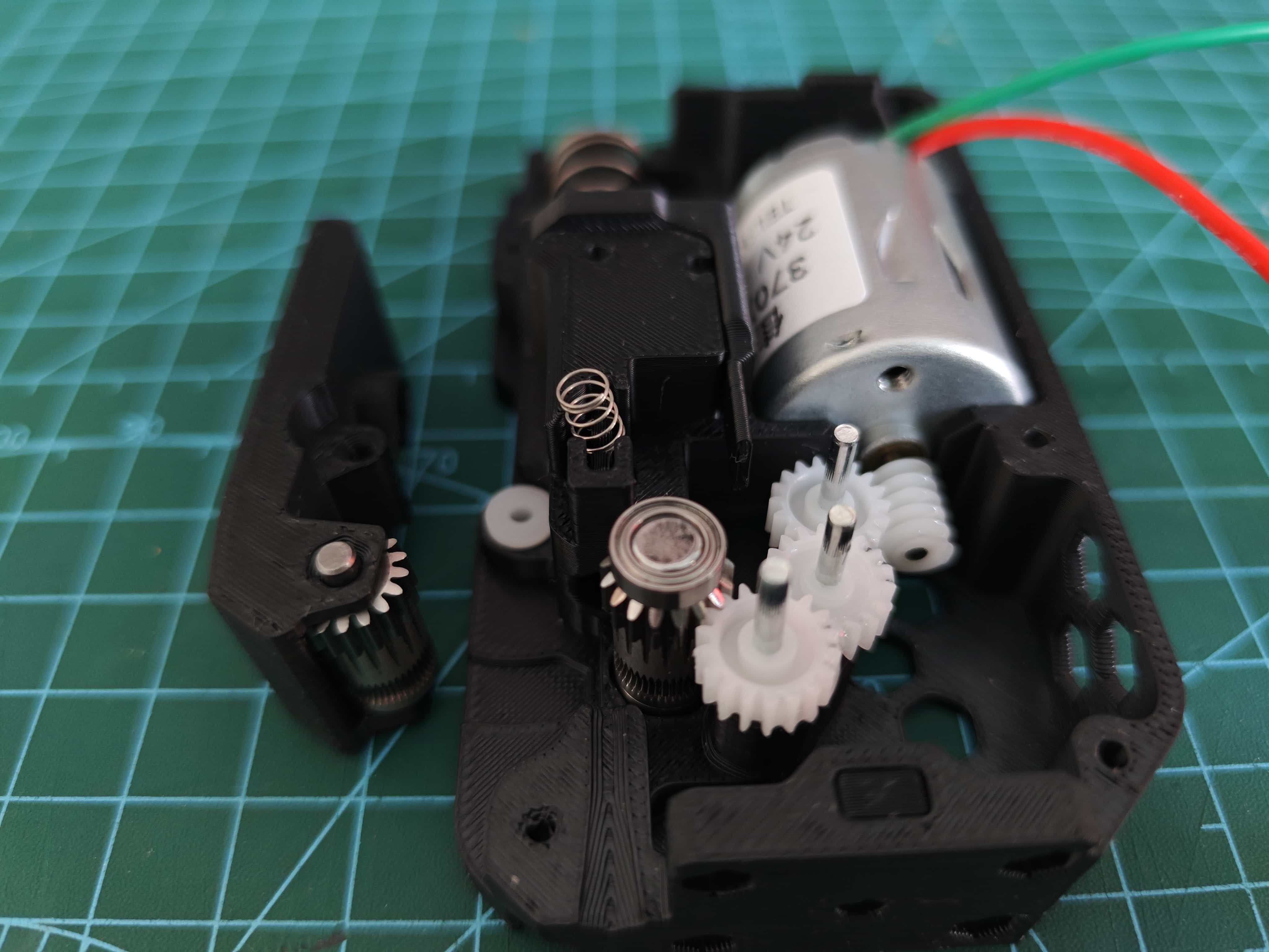
¶ Installing the Motor and Gear
Place the motor and the gear into the back frame.
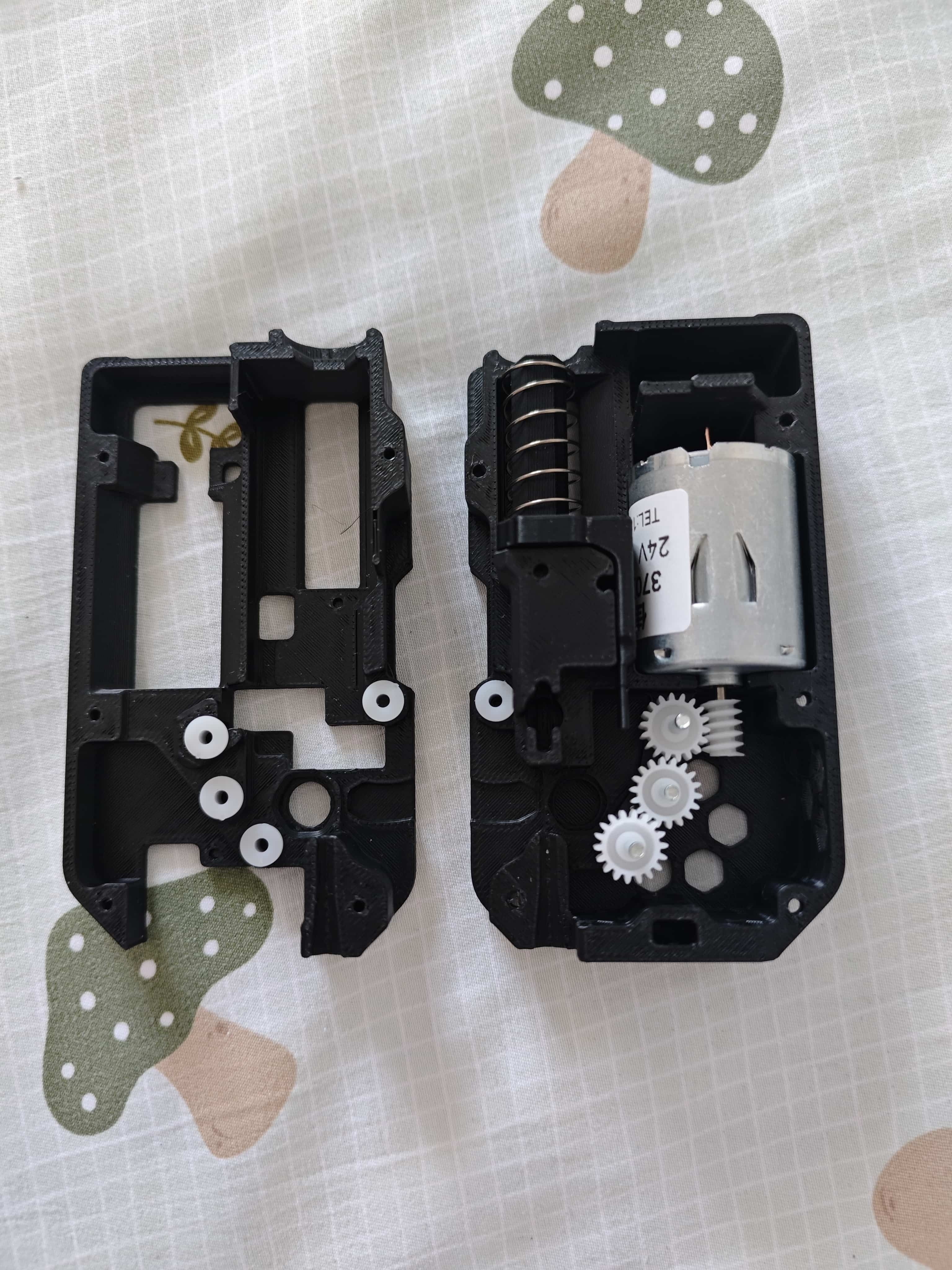
Use a screwdriver through the bottom hole and secure the 370 motor with an M3x5 flathead screw.
¶ Installing the Filament Break Detection Section
Place the steel ball into the back frame.
Then insert the steel ball slider.
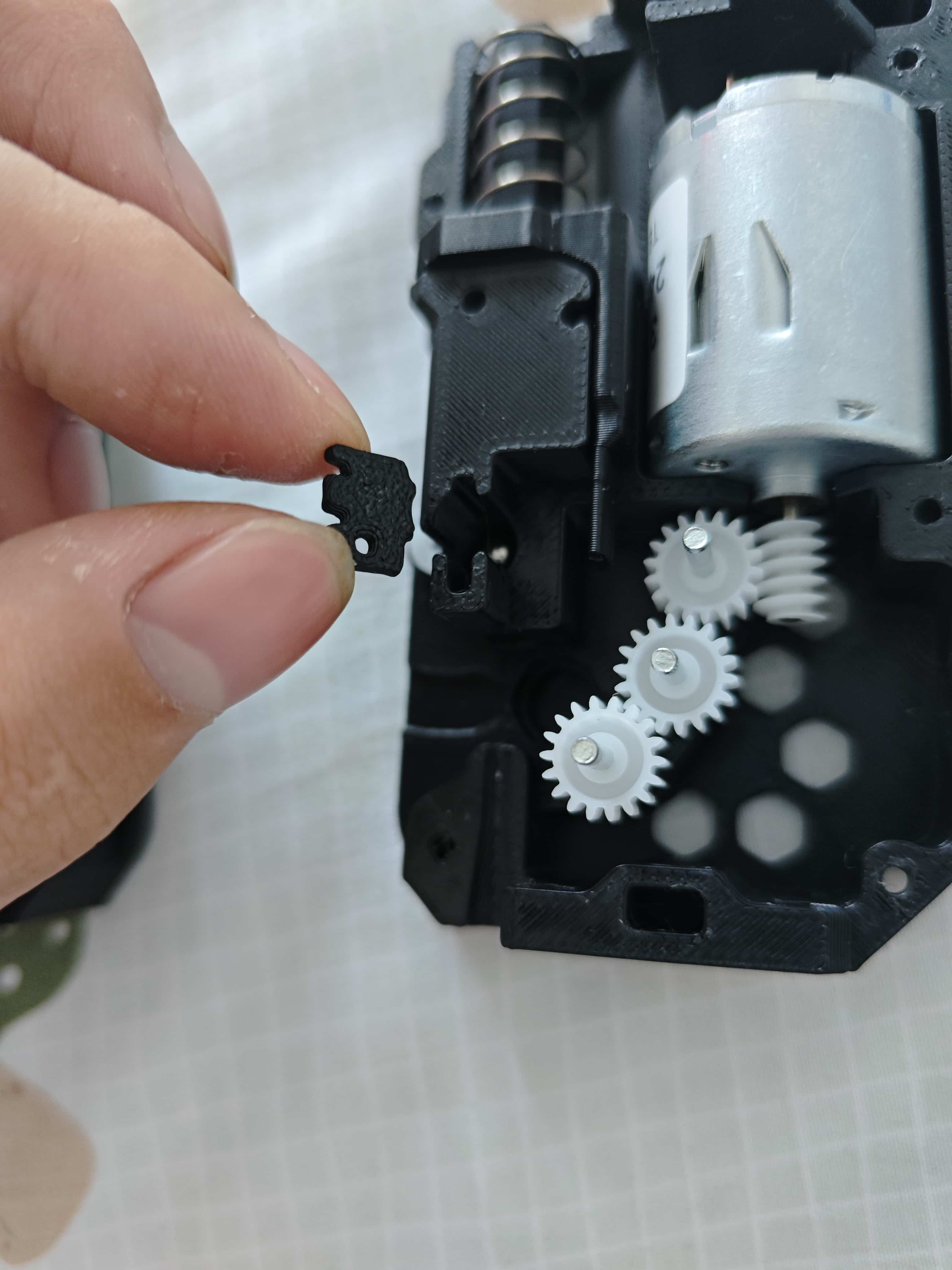
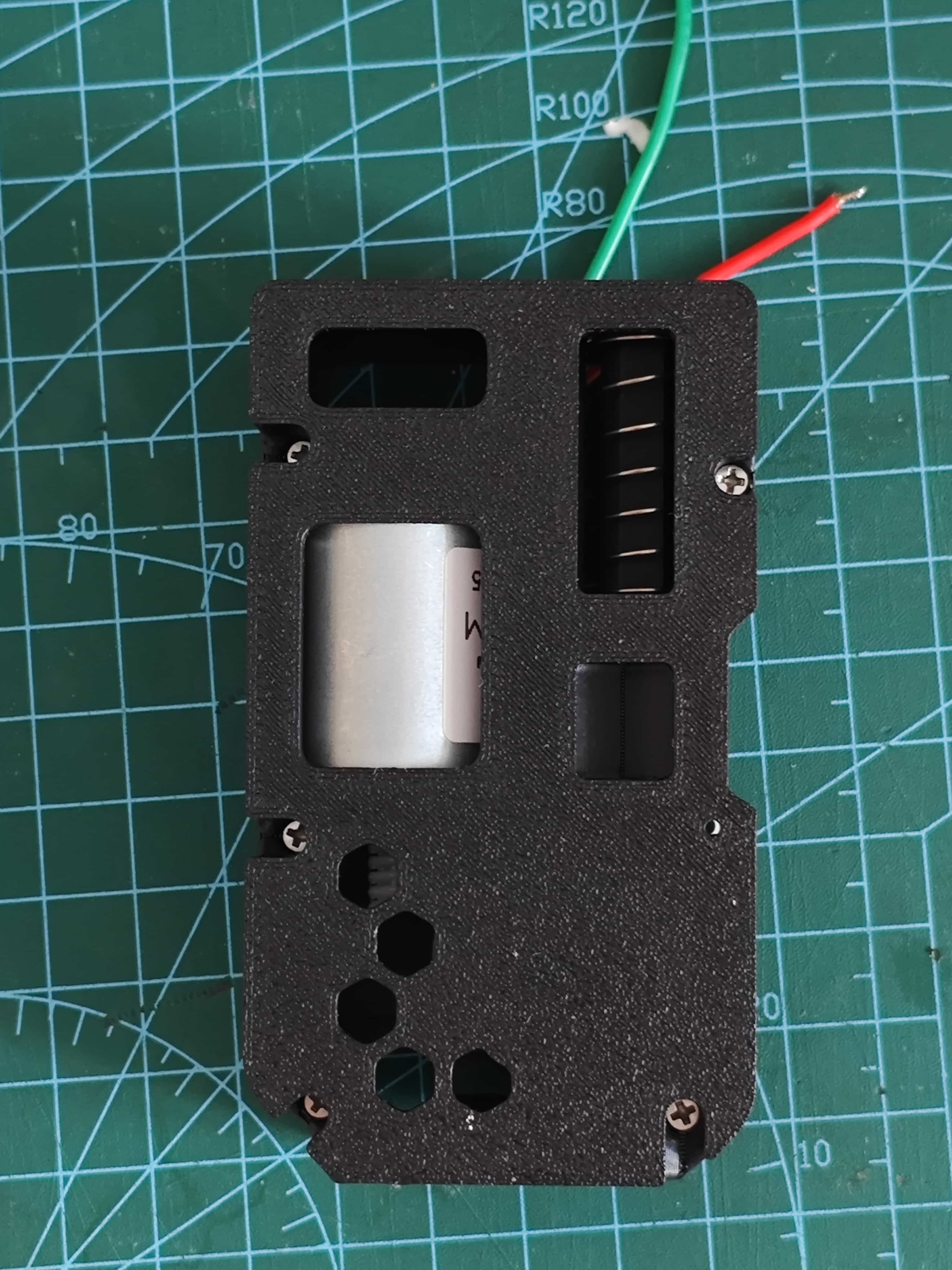
¶ Installing the Hex Nut
In version 3-14, self-tapping holes are replaced with nuts to prevent thread wear from frequent disassembly.
Insert the hex nut into the back cover.
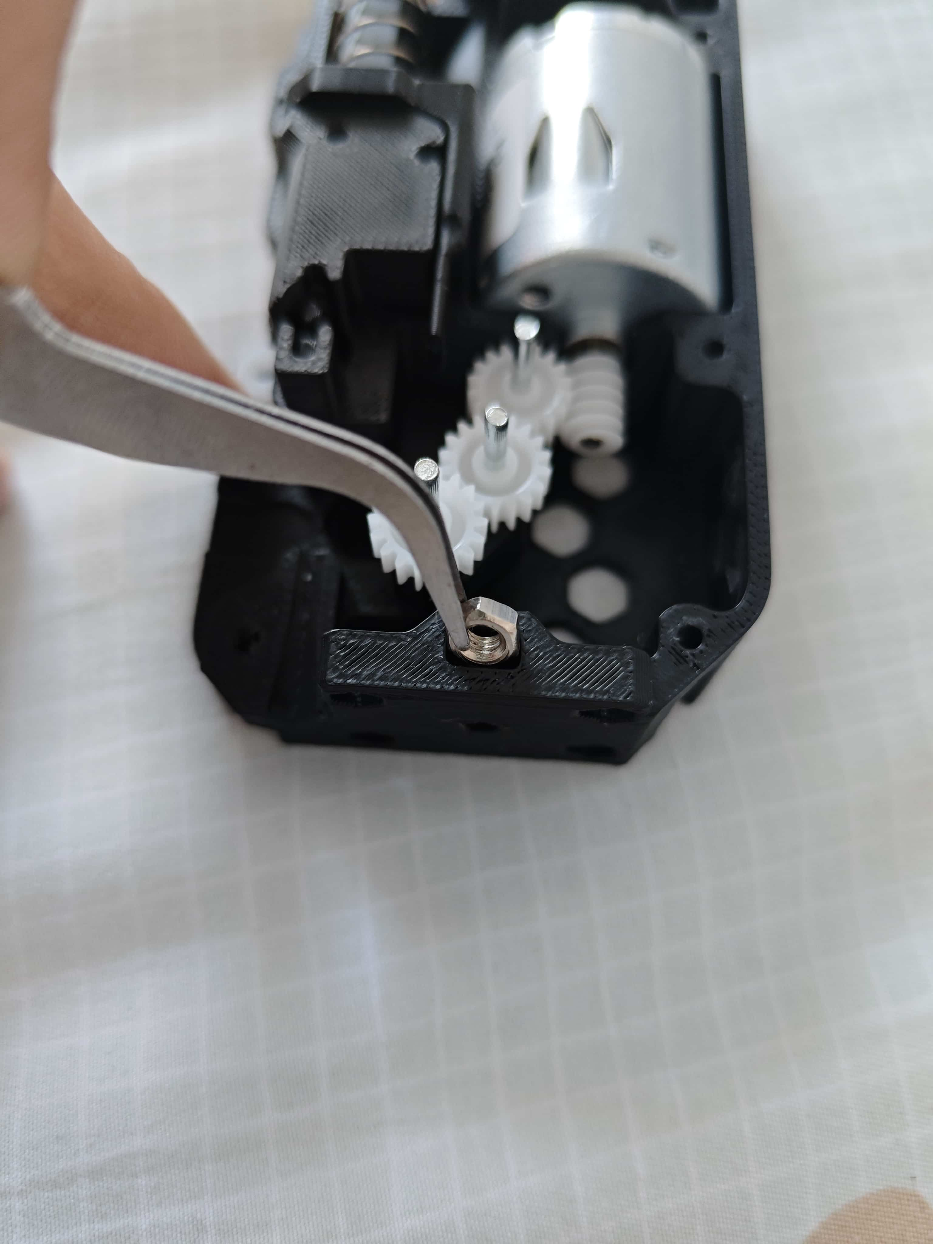
Secure it with the nut insert.
¶ Assembling the BMG Drive Gear
These are all the parts included in the BMG gear set:
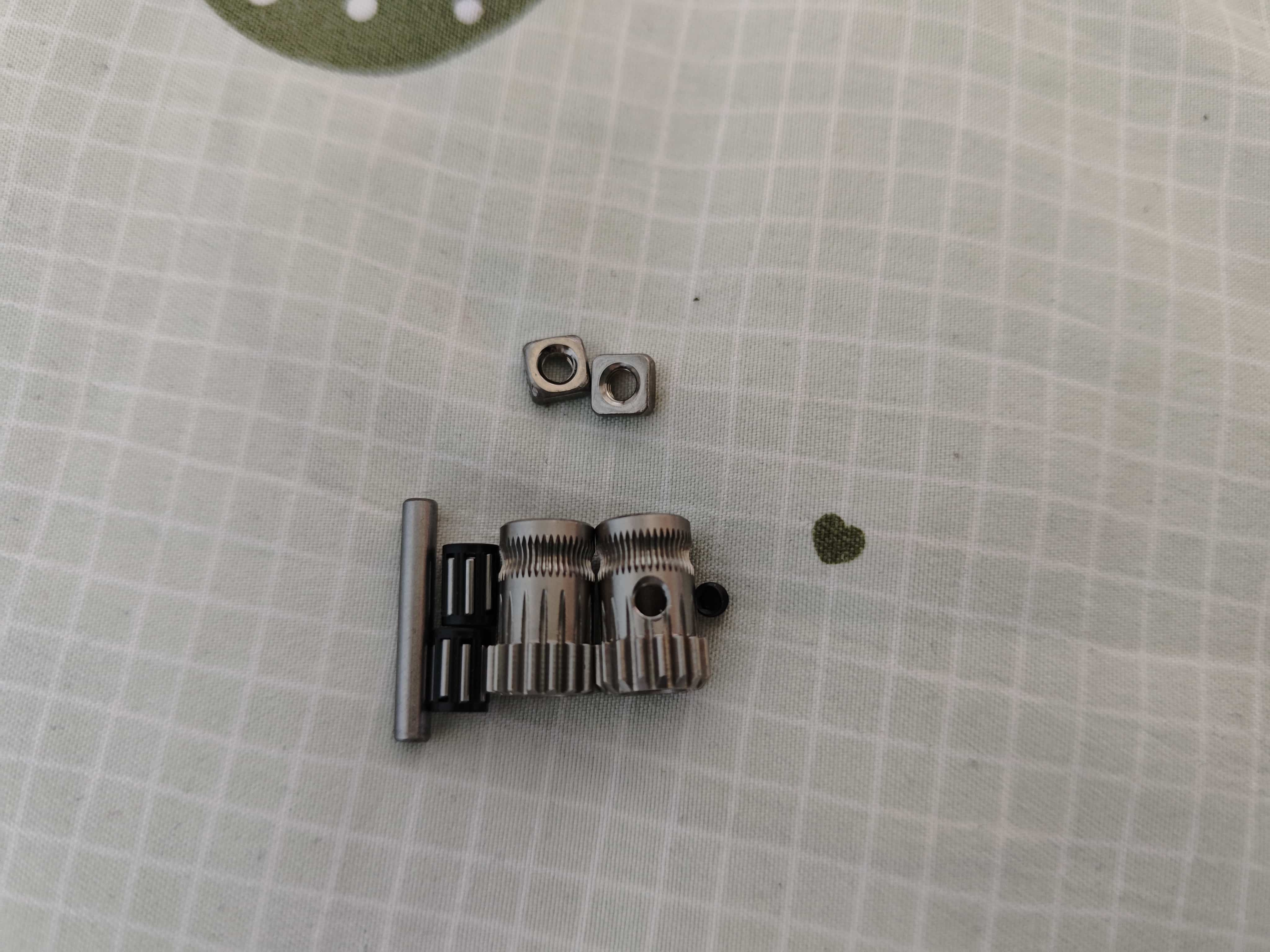
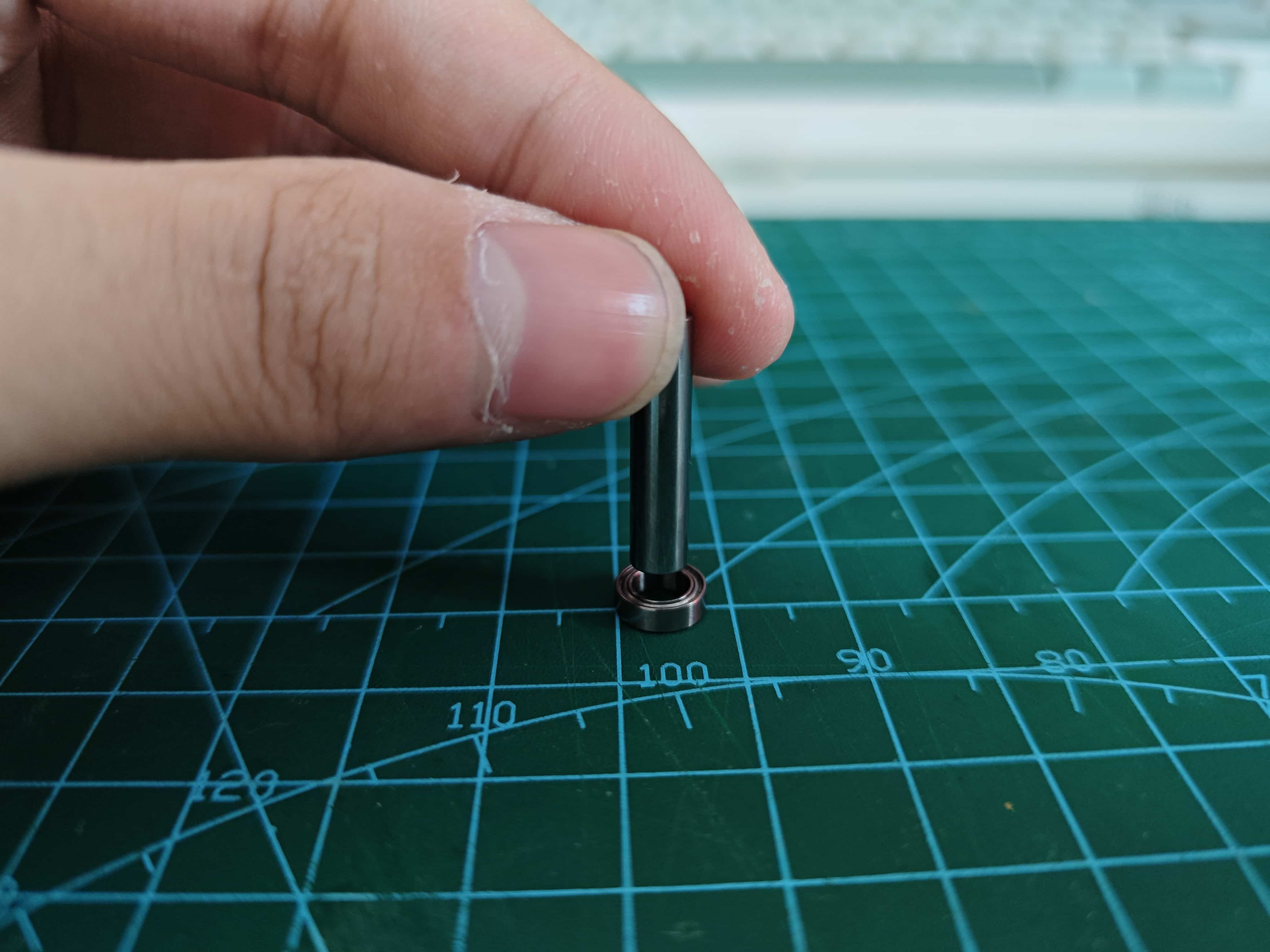
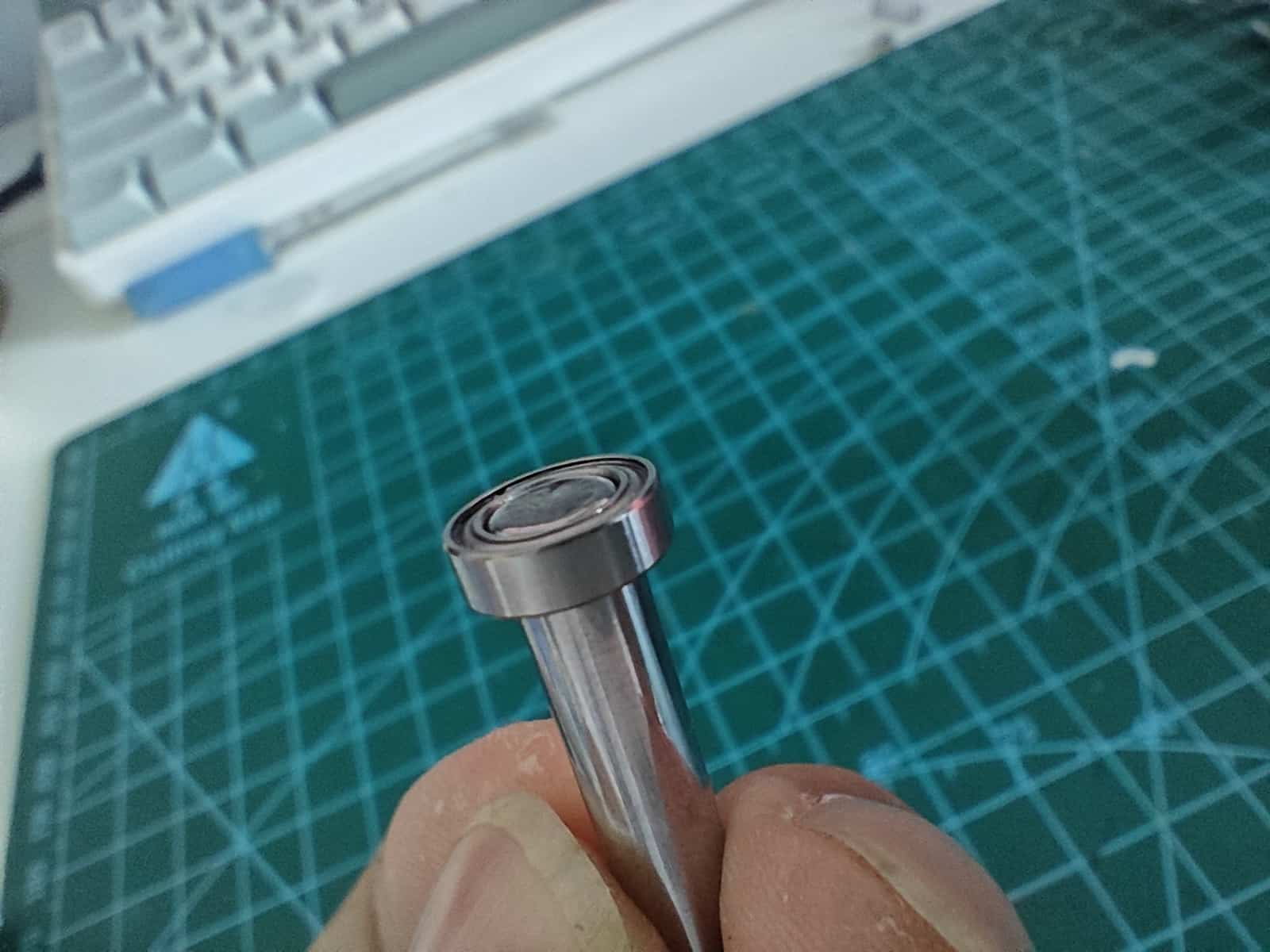
Take one D5x22mm shaft and two MR85ZZ bearings. Press the shaft into one bearing until flush.
Apply even force during installation. Install the shaft vertically to avoid damaging the bearing. Check shaft precision before use—some may not be perfect.
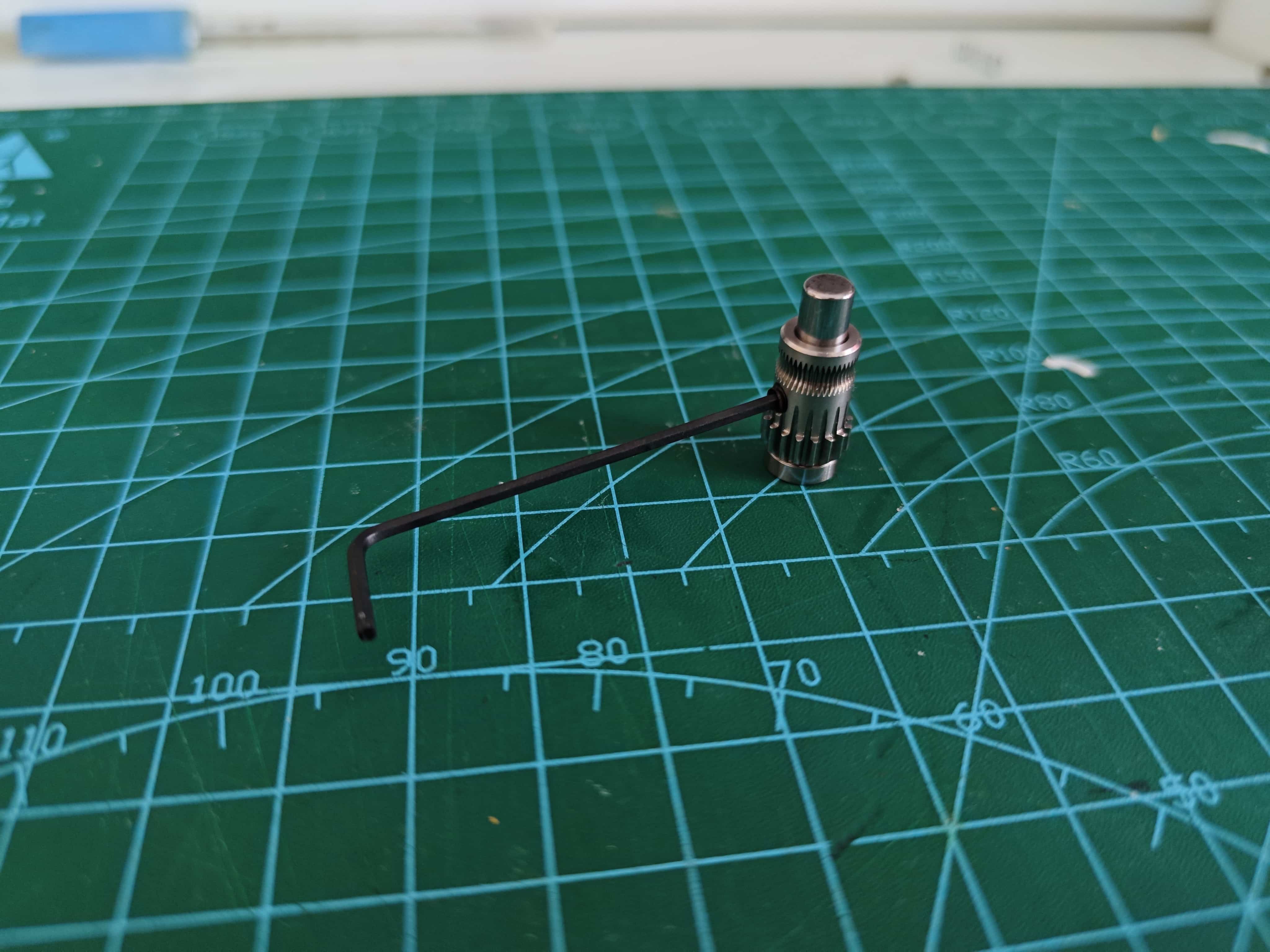
Place the BMG gear with set screw hole as shown:
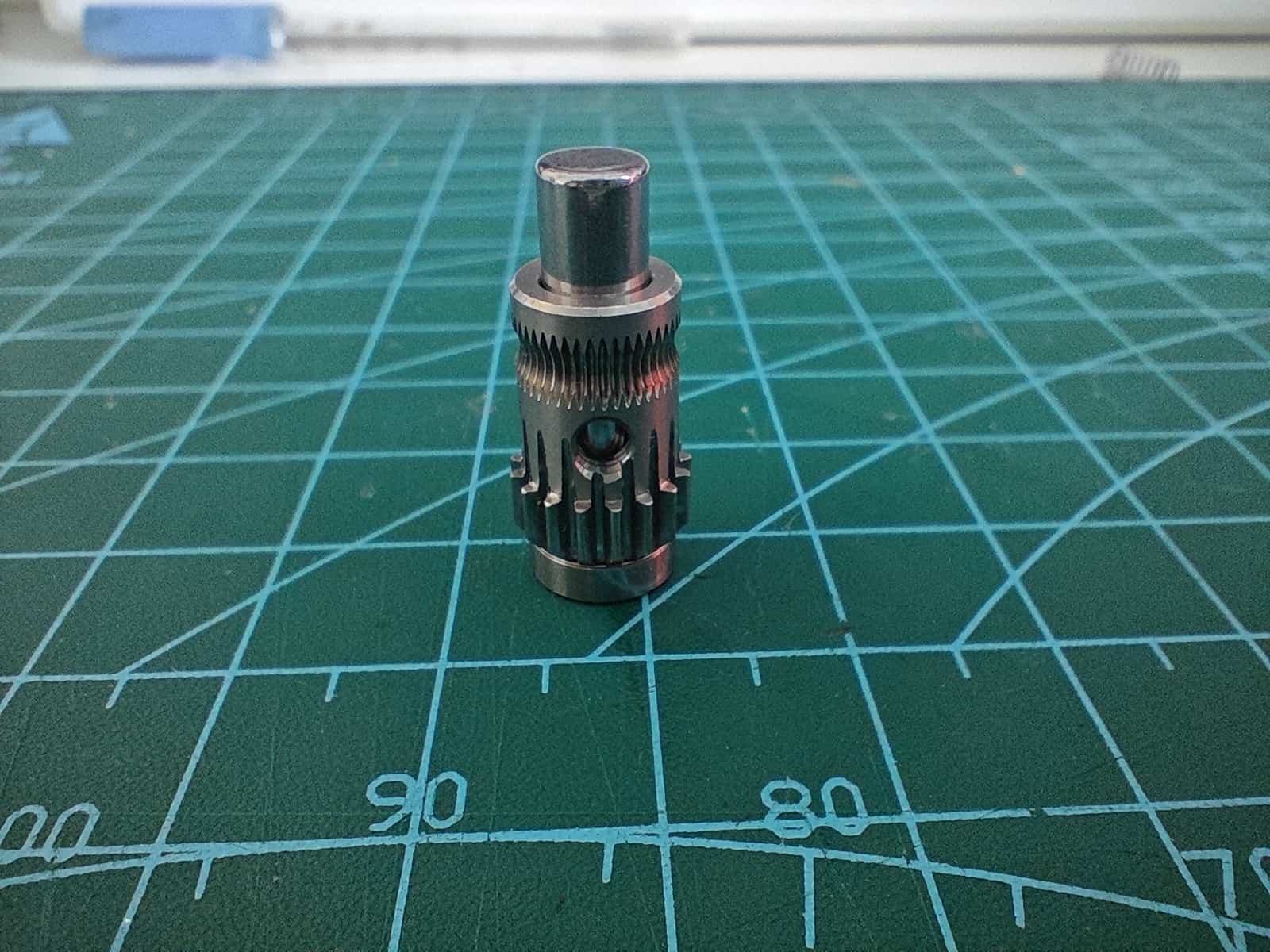
Insert the set screw using a hex key.
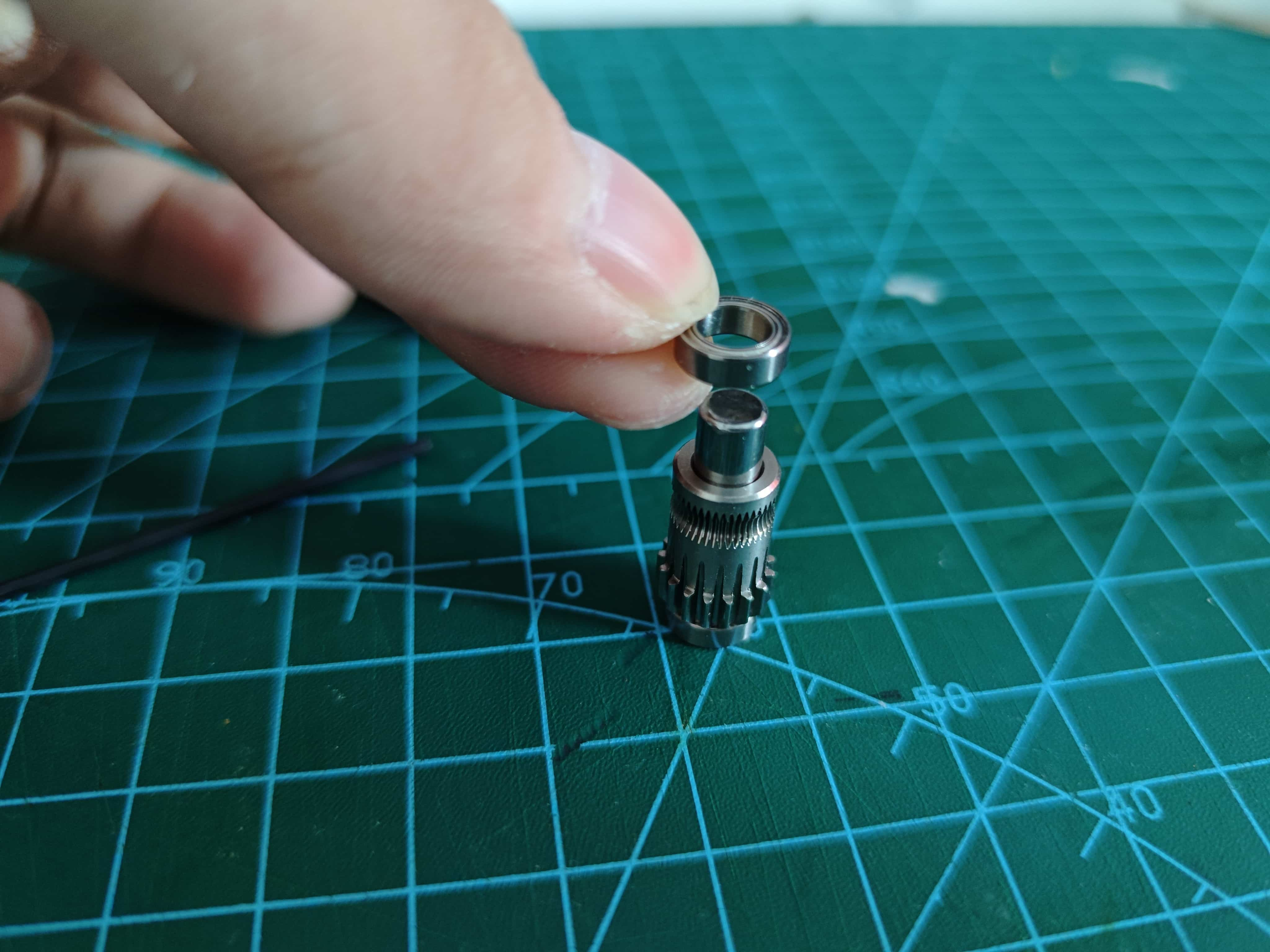
Install the top bearing, ensuring it sits flush against the gear.
Place the assembled BMG drive gear into the back frame, gear facing upward.
¶ Assembling the BMG Driven Gear
Insert two needle bearings into the Driven gear (no set screw hole).
Place it into the lever, making sure the direction is correct, and insert the shaft from the BMG kit.
¶ Lubricating the Gears
I used "Tiger Head" hinge and slideway grease. Do not use oil—only grease.
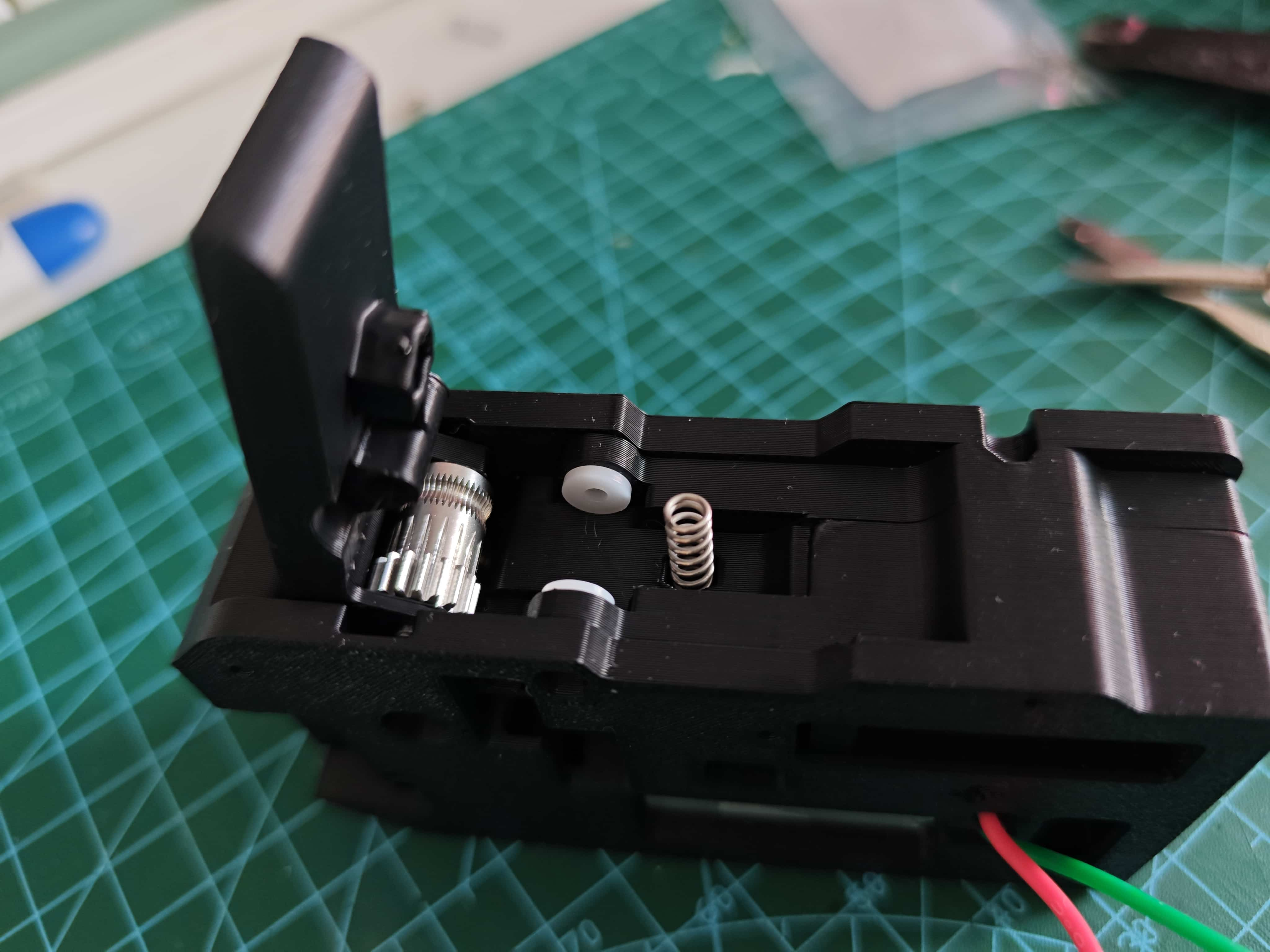
¶ Insert the Steel Ball Spring
¶ Closing the Middle Frame
Secure the middle frame with M2x8 screws.
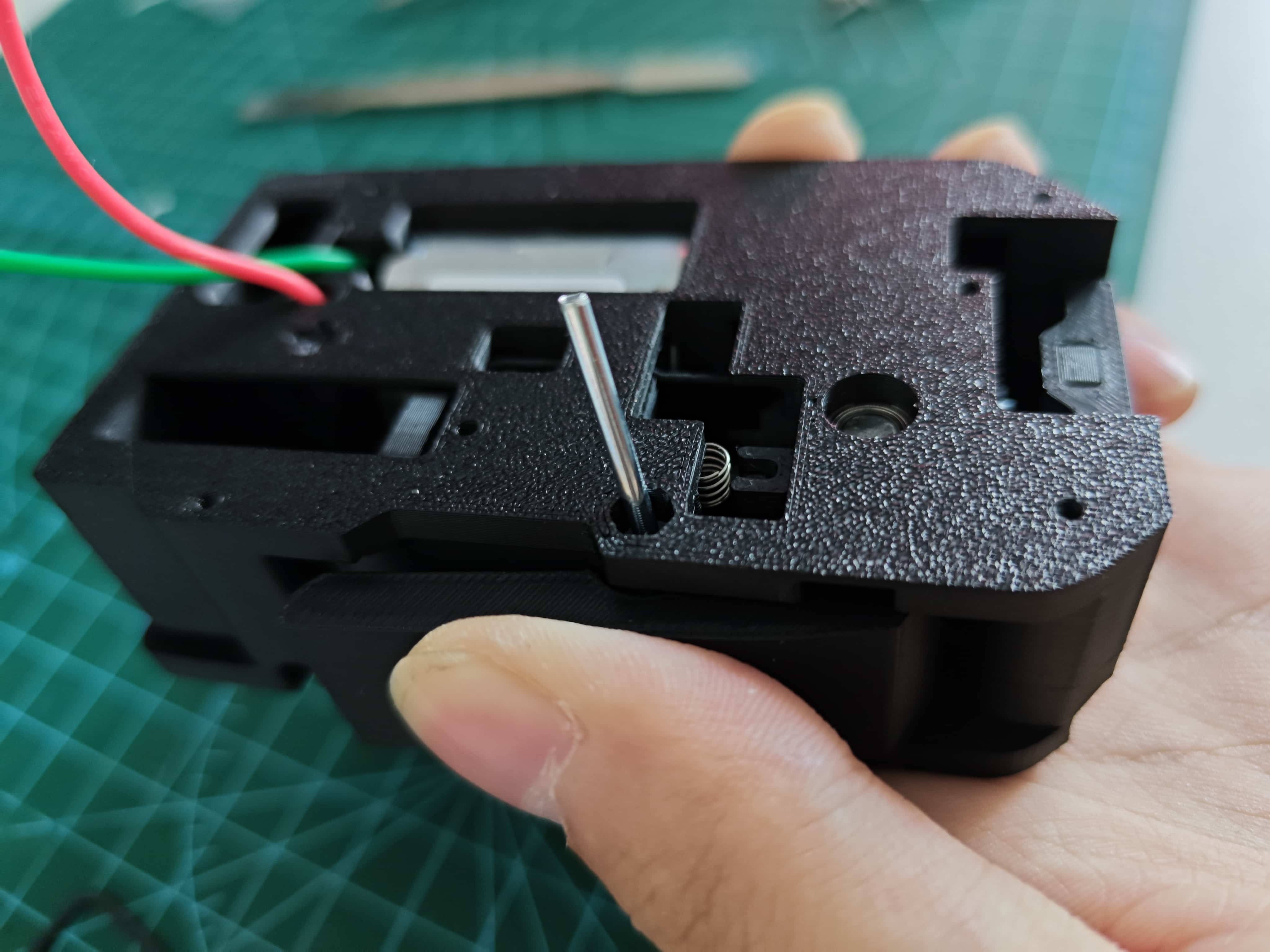
¶ Installing the Lever
Place the lever into the assembly and insert a 0.6*4x10mm spring.
Press the lever down and insert a 2x20 shaft to lock it in place.
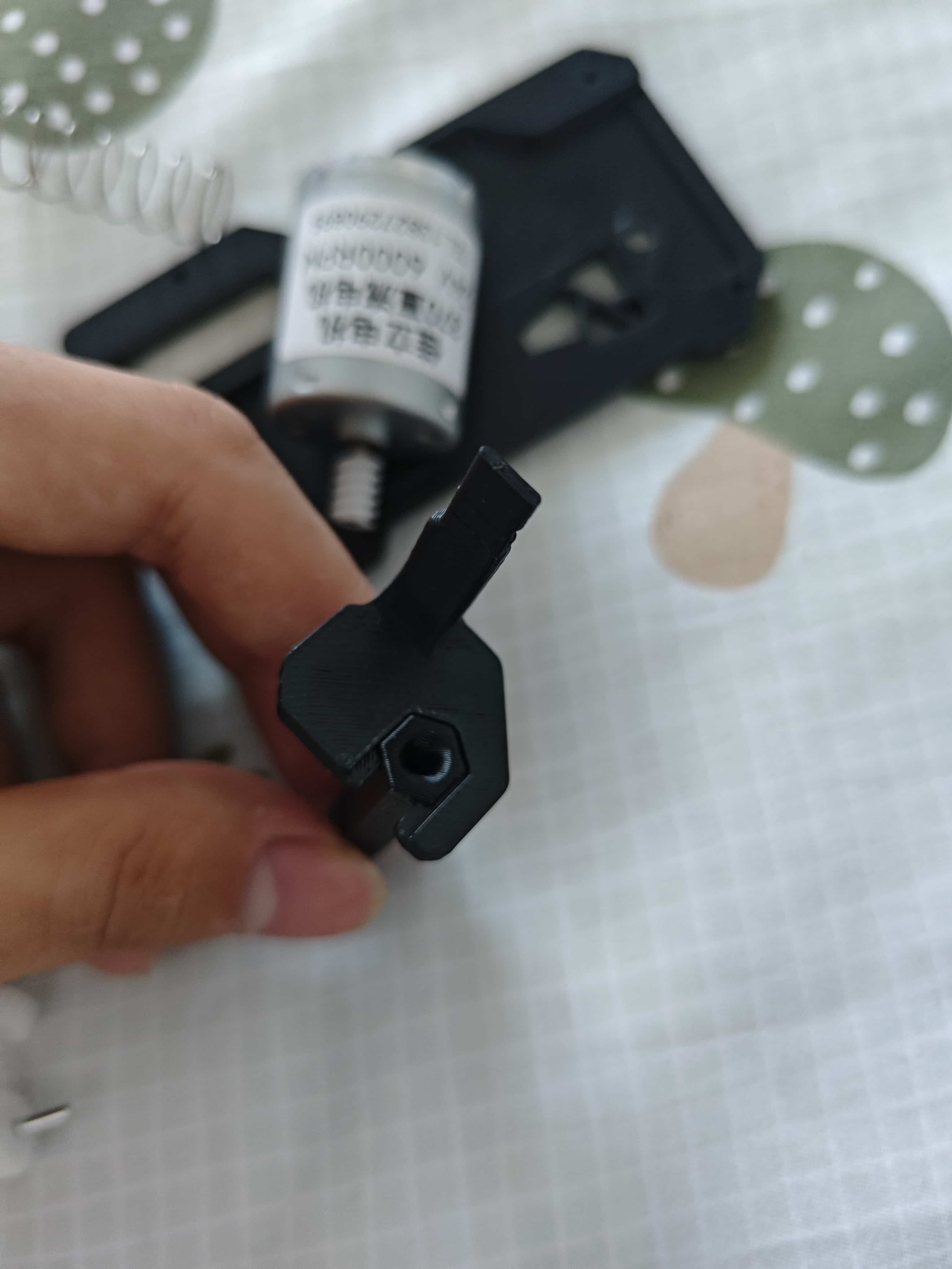
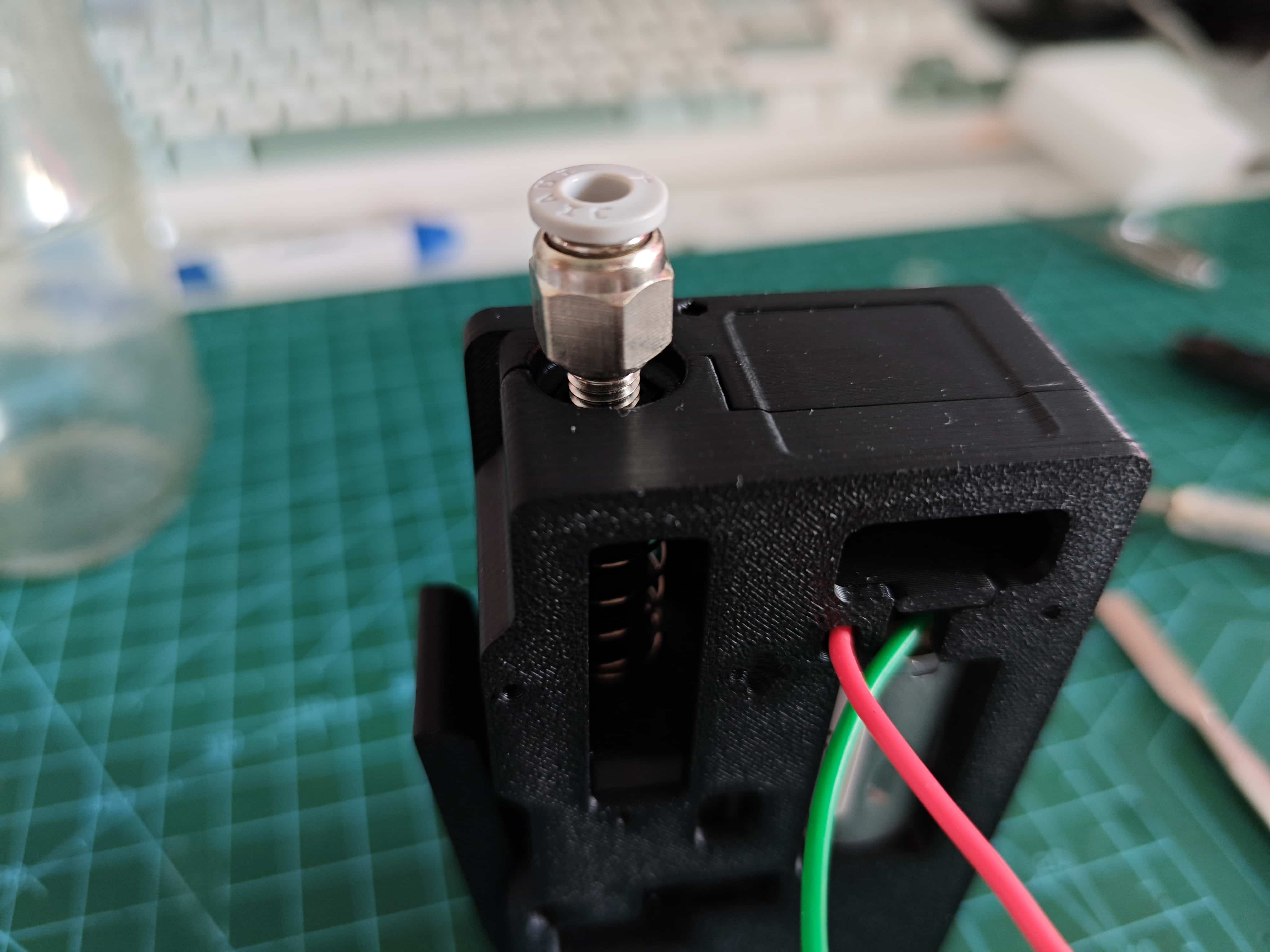
¶ Installing the Pneumatic Connector on the Buffer
Screw the connector into the buffer.
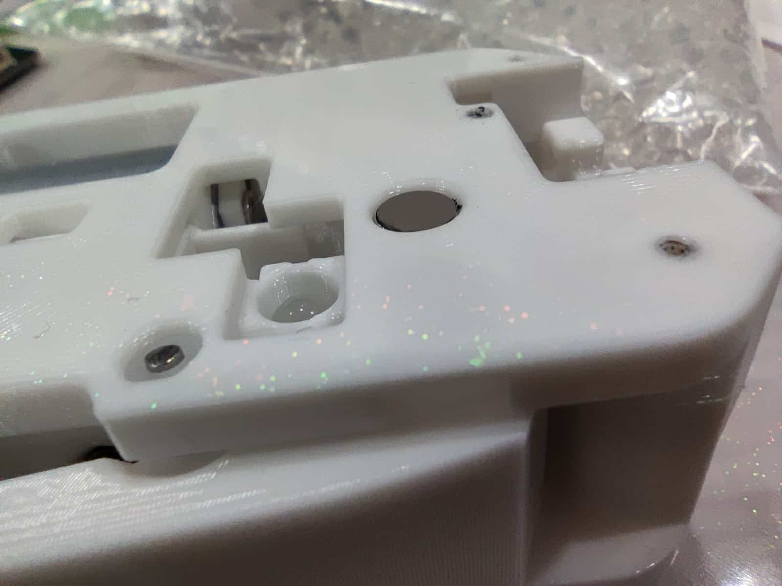
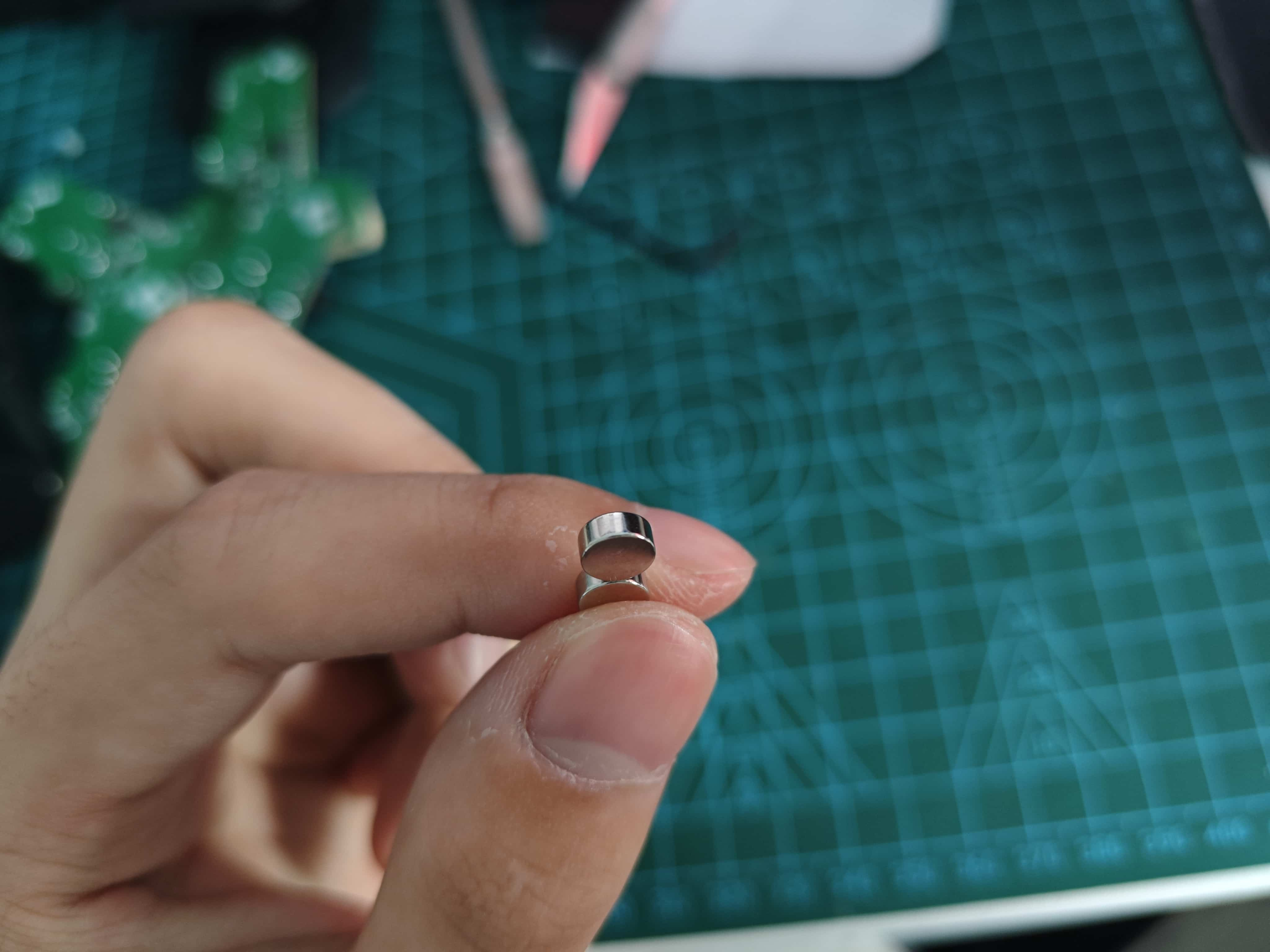
¶ Installing the Radial Magnet
Place the radial magnet into the slot on the middle frame. Ensure it sits slightly below the surface.
(Illustration borrowed from the 370X version, but it's the same process)
¶ How to Identify Radial vs. Axial Magnets
Radial magnets have stronger side pull and can spin freely when held sideways.
At this stage, insert filament and power the motor with 12V~24V to test:
- Can it pull filament?
- Does the magnet spin correctly?
- Does the grease distribute evenly?
You can insert an optical fiber into the small hole next to the buffer as a light guide.
¶ Installing the Circuit Board and Final Testing
¶ Assembly
- Place the secondary board (sensor side down) onto the middle frame and secure with two M2x8 screws.
- Attach the front frame with four M2x8 screws.
- Connect the secondary board to the main board via ribbon cable.
- Connect the main board to your computer using a USB-to-TTL module (power and ground are enough). You can also wire it the same as during firmware flashing.
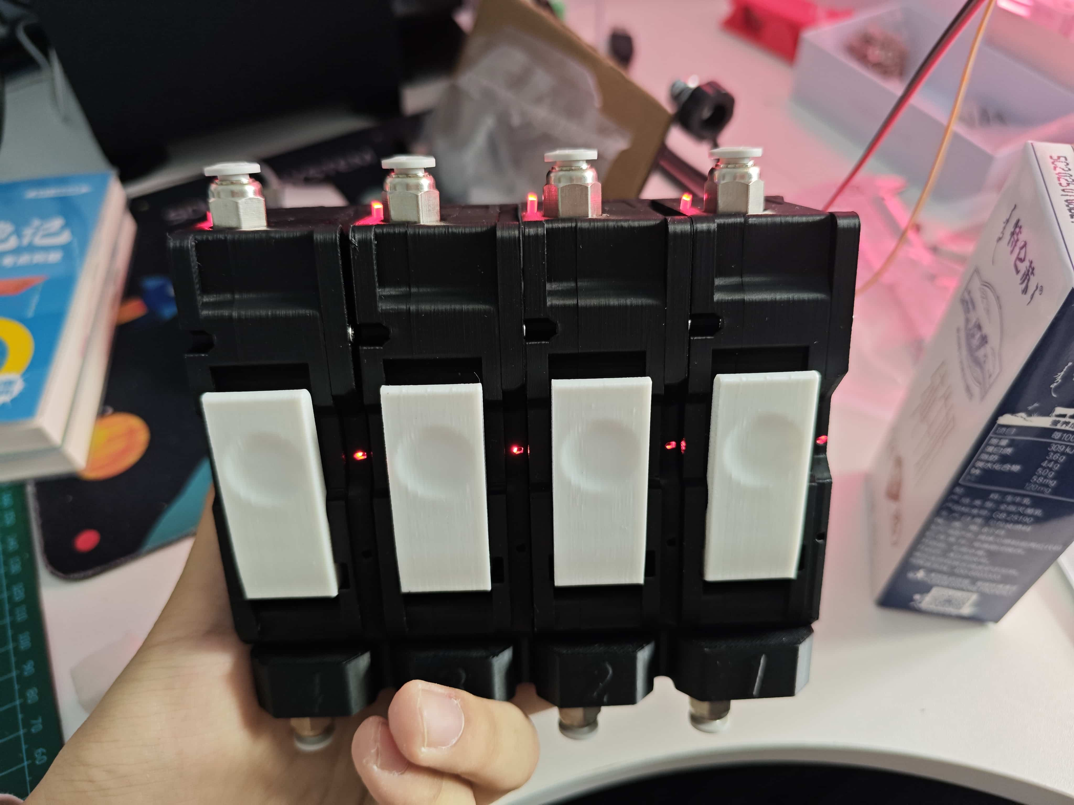
¶ Testing
My pictures show the fully assembled unit, but I recommend testing after building one channel to avoid unnecessary trouble.
Initial power-up status (main board not shown, red LED on main board):
Secondary board WS2812 red, buffer light ON, filament sensor OFF
Press the lever, insert filament, then release:
Secondary board WS2812 red, buffer light ON, filament sensor ON
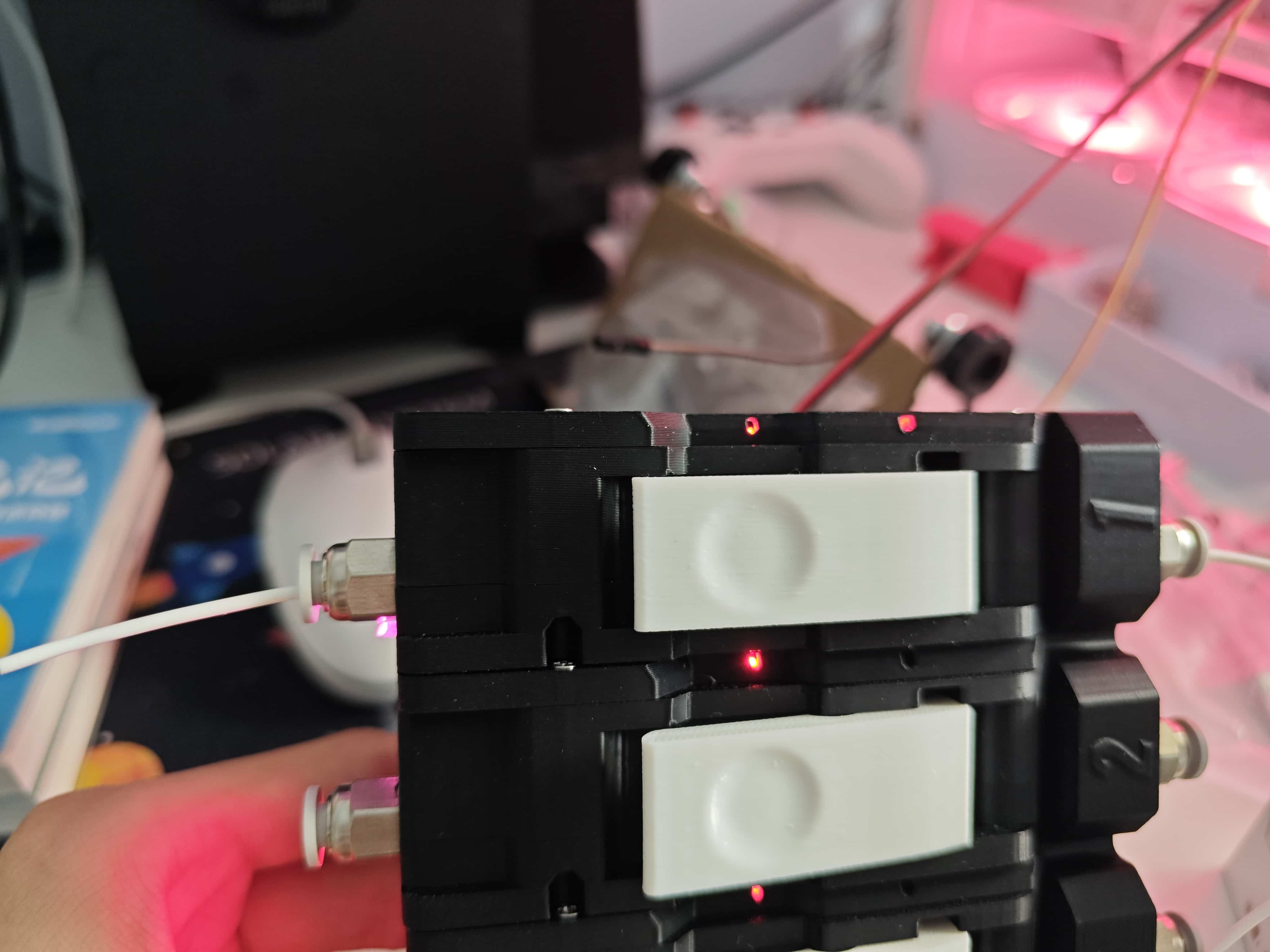
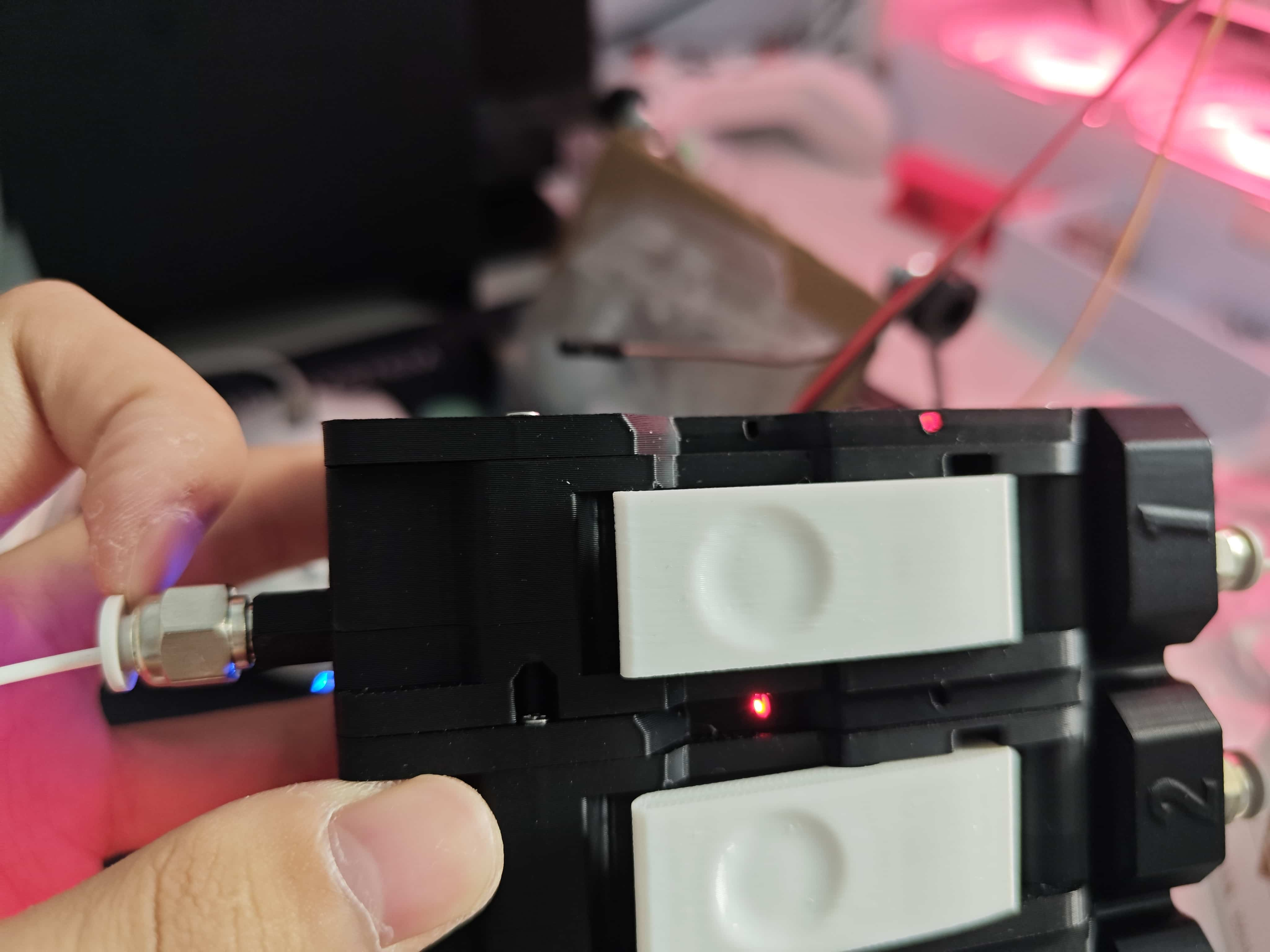
Now pull the buffer open:
Secondary board WS2812 red, buffer light OFF, filament sensor ON
¶ Installing the Feeding Assembly and Circuit Board to the Base
Very simple—refer to the image below:
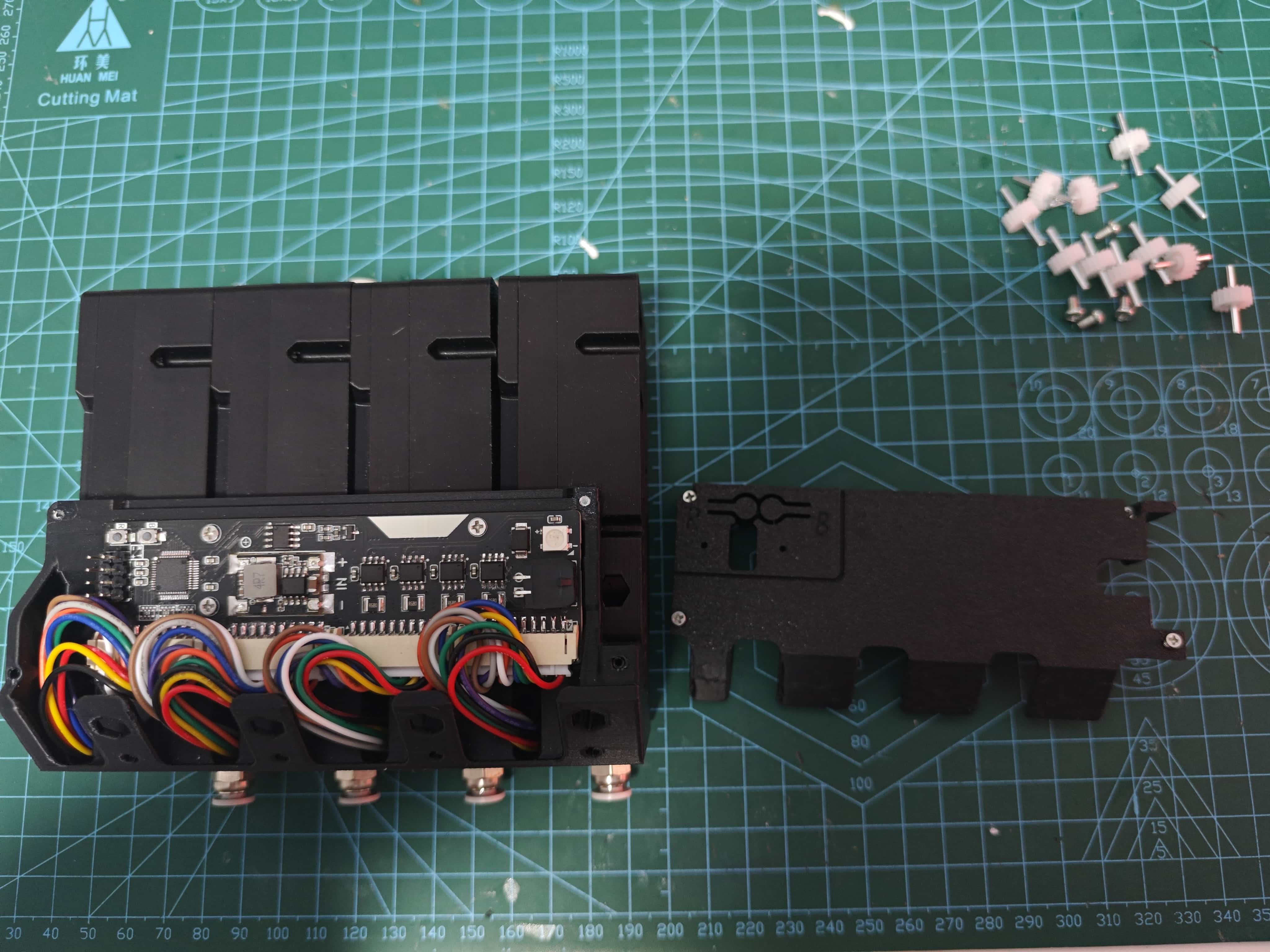
- Secure the main board with three M2x8 self-tapping screws.
- Use four M2x8 screws to secure the main board cover.
- Fix the feeding assembly to the base using M3x14 flathead screws.