¶ Preamble
The tutorials on this page are adapted to the following models posted on my makerworkd.
The 370 version is currently in a period of rapid iteration, with updated beta versions being produced daily. This version is the official version released by the author some time ago.
With this version you will use:
- 0.6*10*30 springs for buffering
- 0.4*6*15 springs for lever
This version may cause a problem with the five-passes being jacked out, this problem is a common problem with the 370 version. Almost all current 370 version will have this just the probleme soon or later, the different versions of model or steel ball versions are just to improve the photoelectic sensor problem.
¶ Model
PLA/PETG or higher strength materials can be used.
It is easier to print with PLA for higher precision, but please be careful not to use too much force when screwing.
https://makerworld.com/zh/models/1189069-bmcu-370-version-original-v2-5#profileId-1200559
¶ 370 version assembling
¶ Step 1 (optional)
Insert the clear consumable through the centre frame and tuck it in firmly until he other end emerges from the middle of the frame.
If conditions permit, a 1.5mm fibre is recommended.
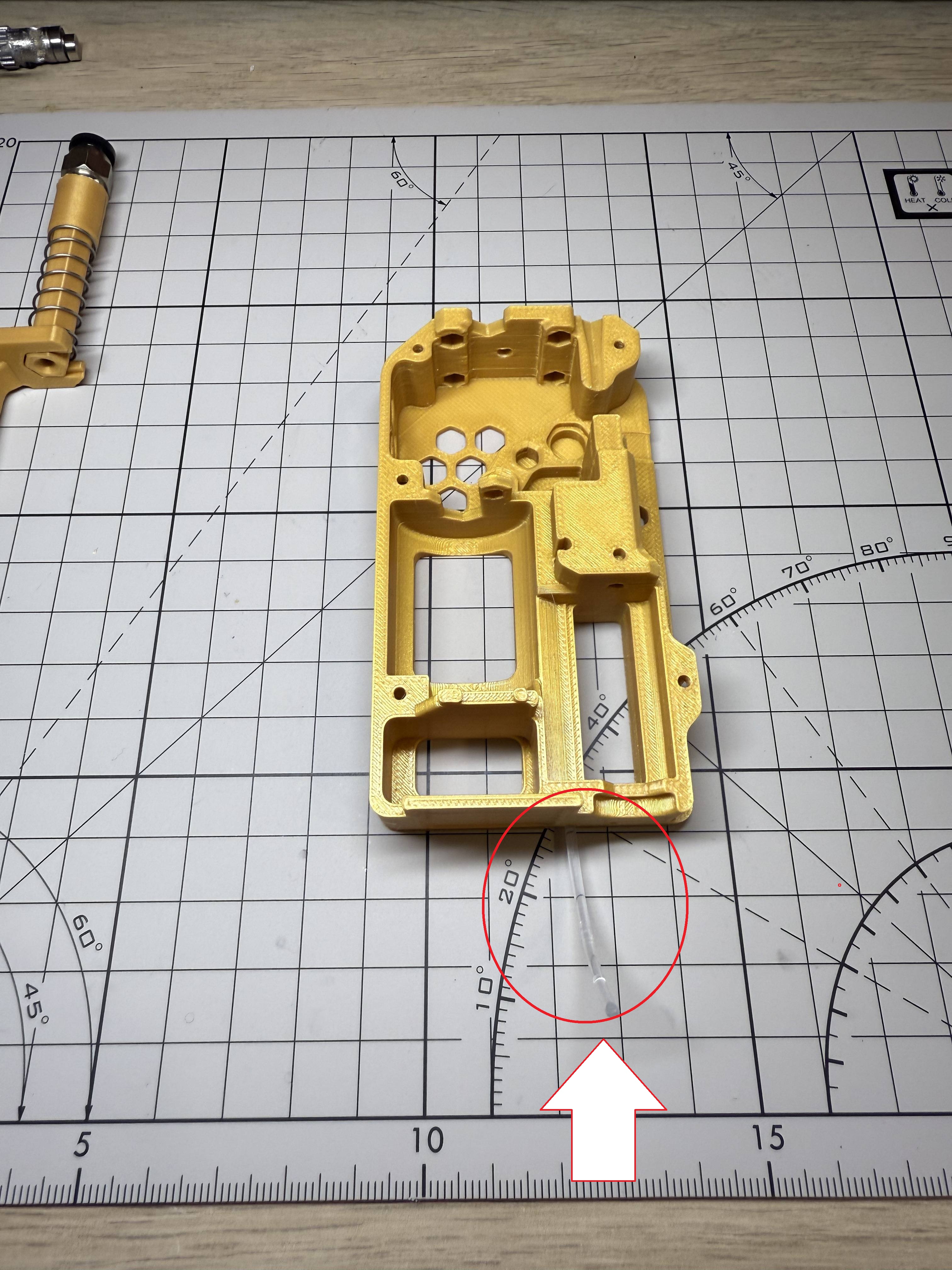
If you don't have transparent filament, skipping this step is not a problem. You can always do this step after the assembly is complete.
¶ Step 2
Get components of the buffer and assemble them
¶ Step 3
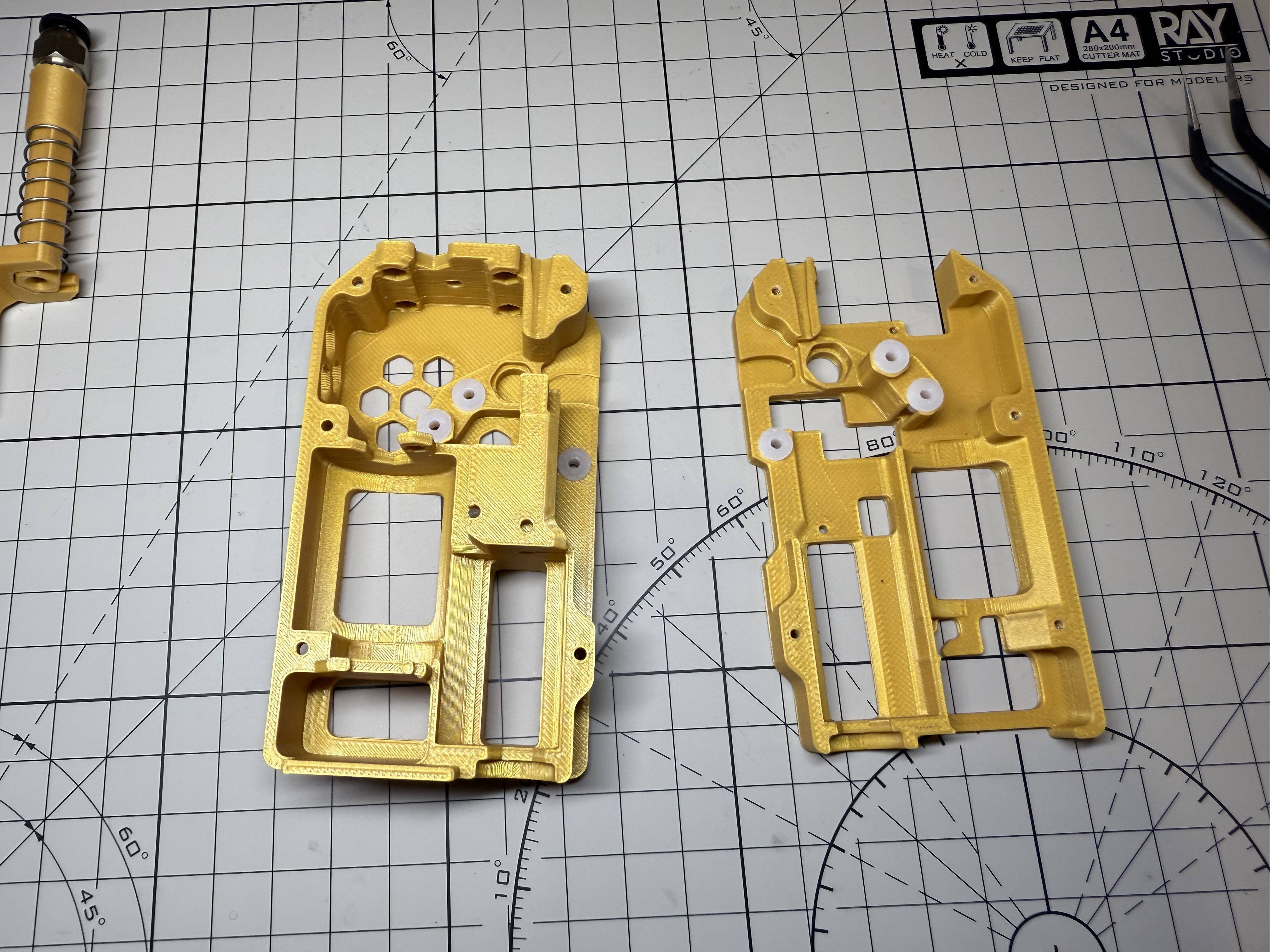
Install all 62B bushings - 6 to install, 3 in the bottom frame, 3 in the middle frame.
¶ Step 4
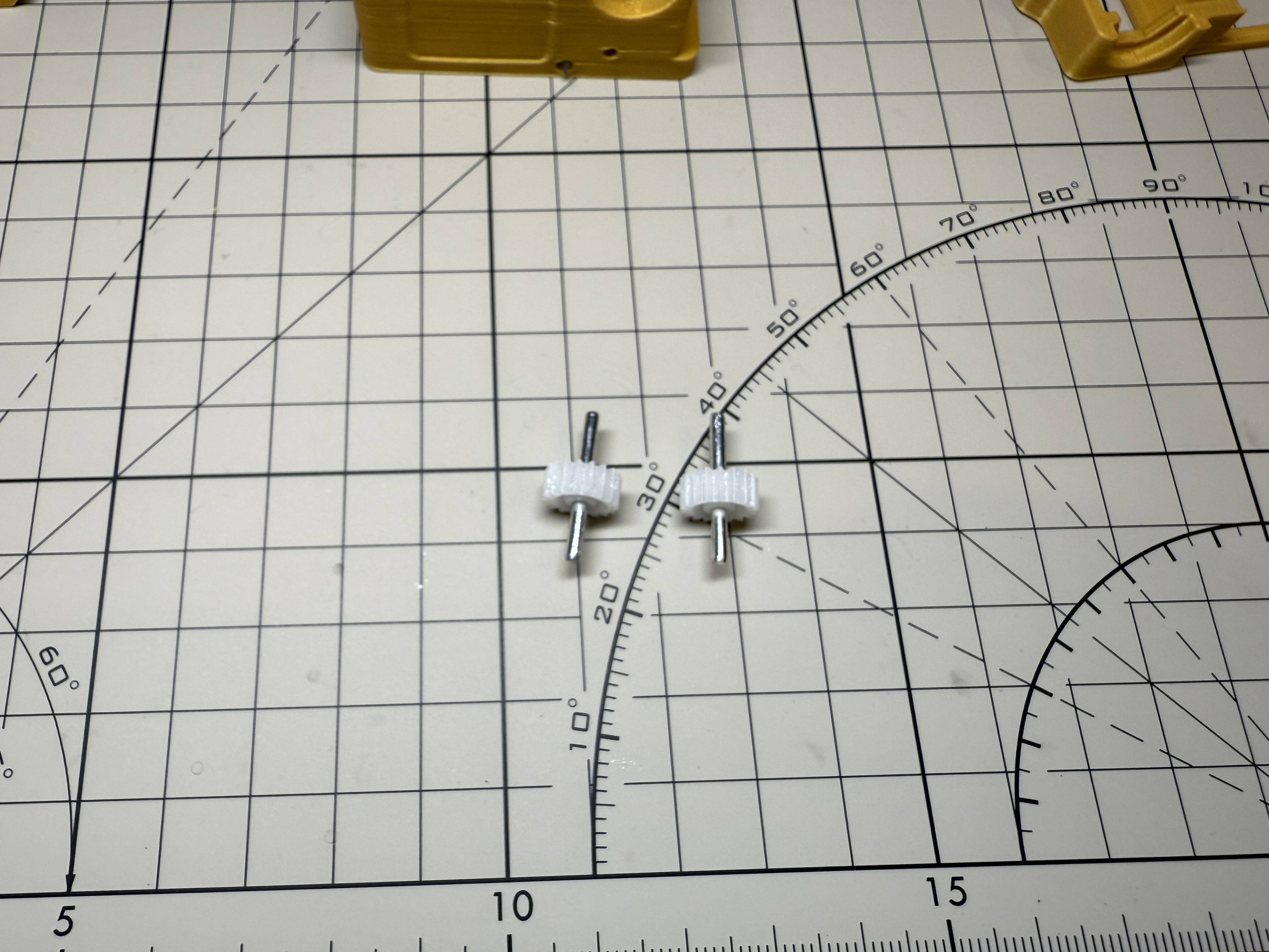
Get two D2*20 shafts and two 182A gears,Get two D2*20 shafts and two 182A gears, then assemble them similar to this
one side should be slightly longer than the other
¶ Step 5
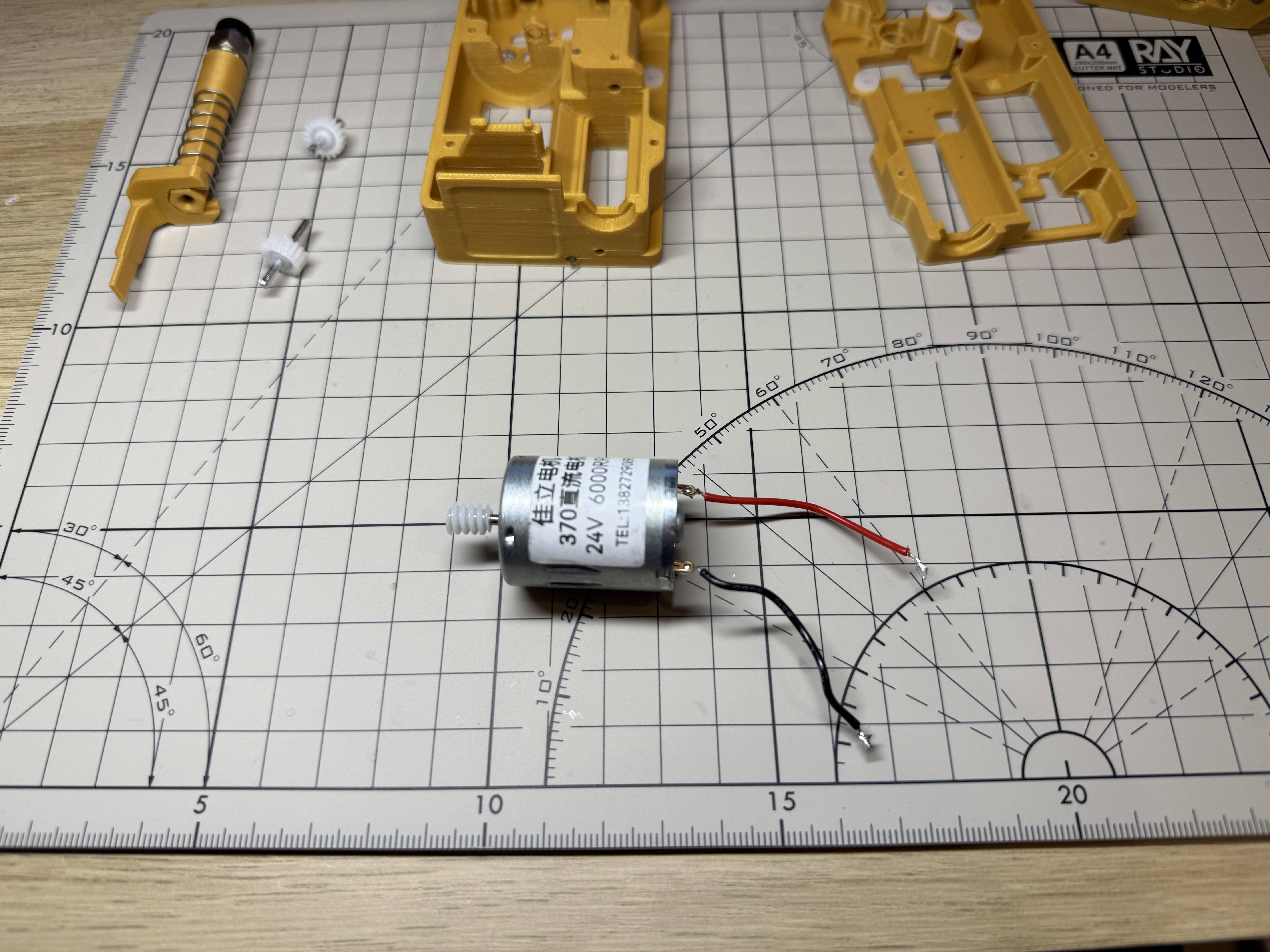
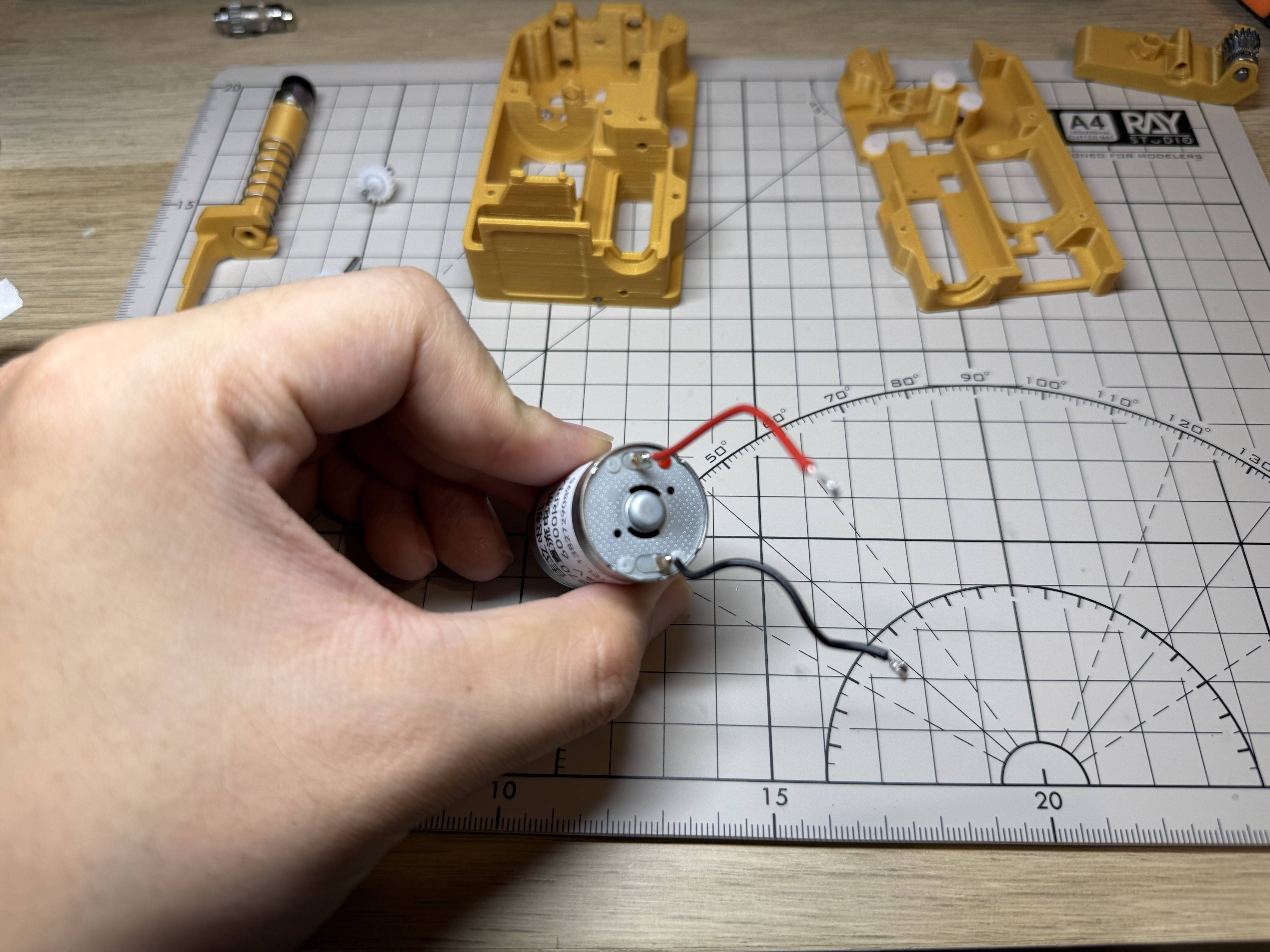
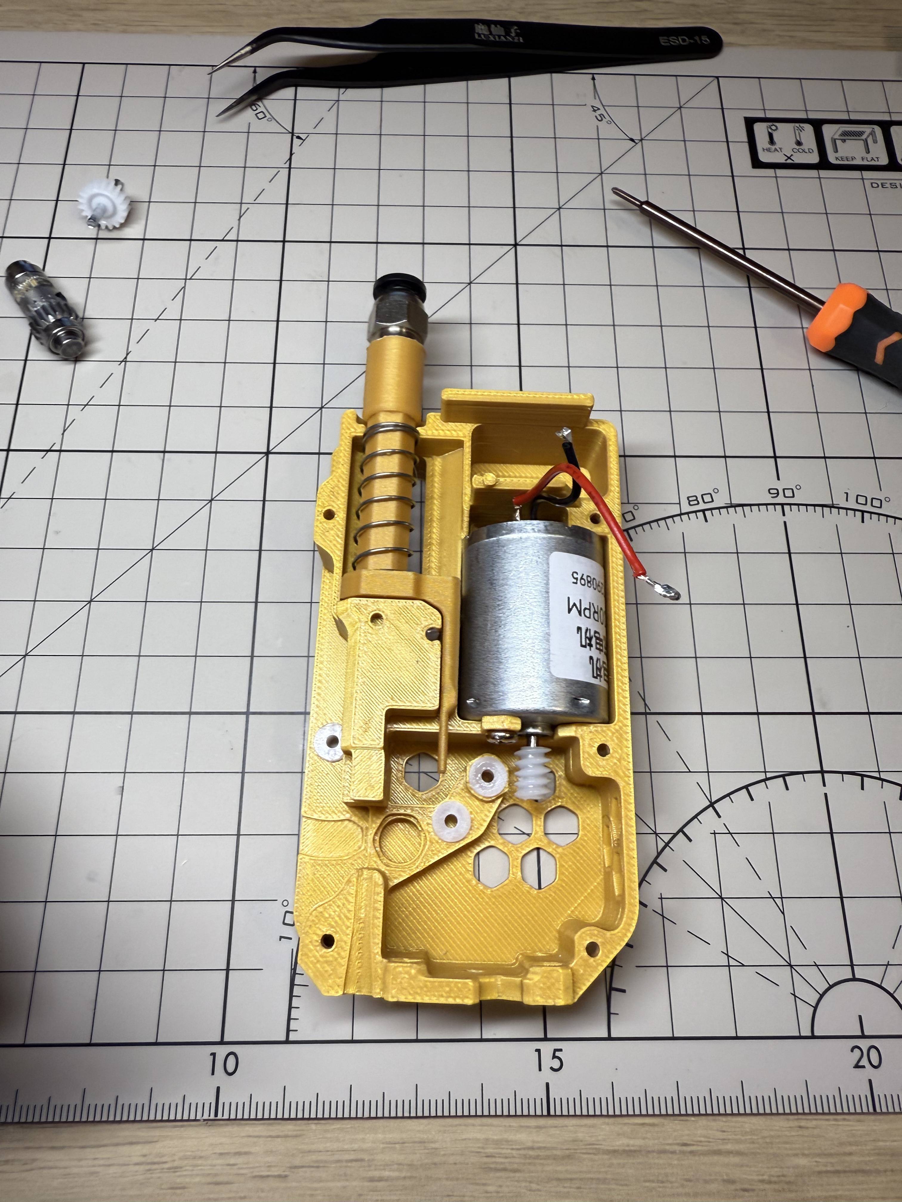
Install the worm gear onto the 370 motor and solder two wires to the motor. The red dot on the motor marks the positive terminal.
One special feature of this 370 version of the model is that the power supply to the motor needs to be reversed, and here I recommend connecting the red wire to the positive terminal of the motor.
¶ Step 6
Secure the motor in the bottom frame with one M3*6 flat head screw.
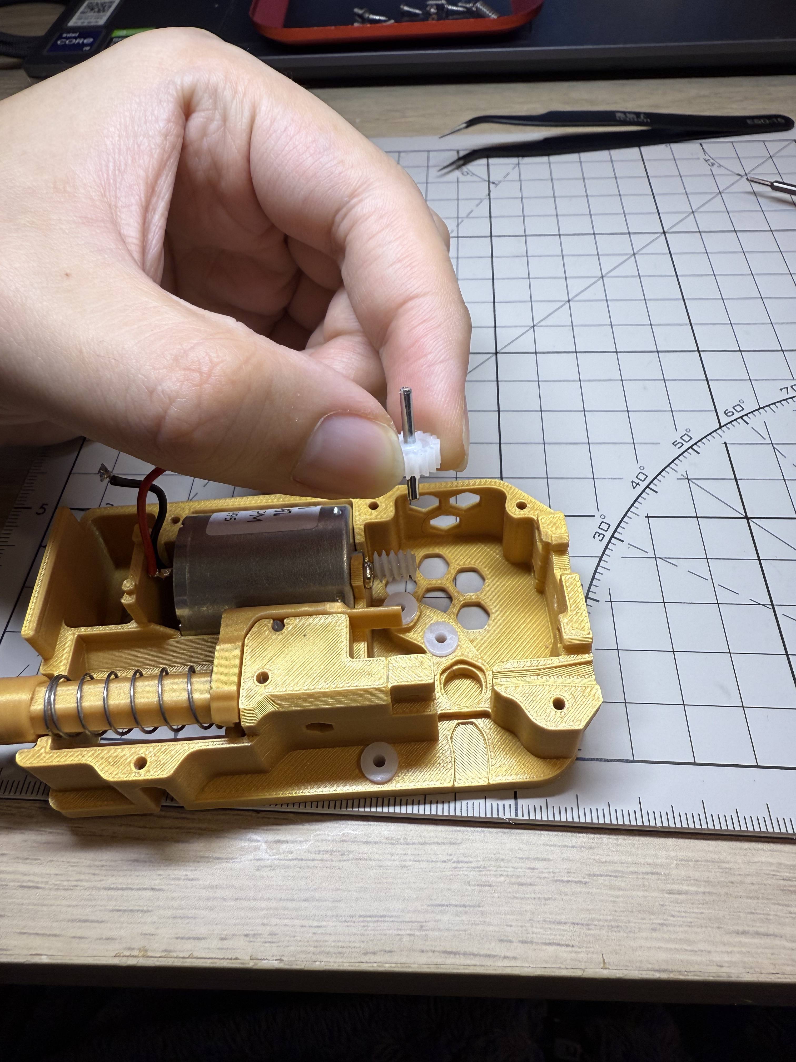
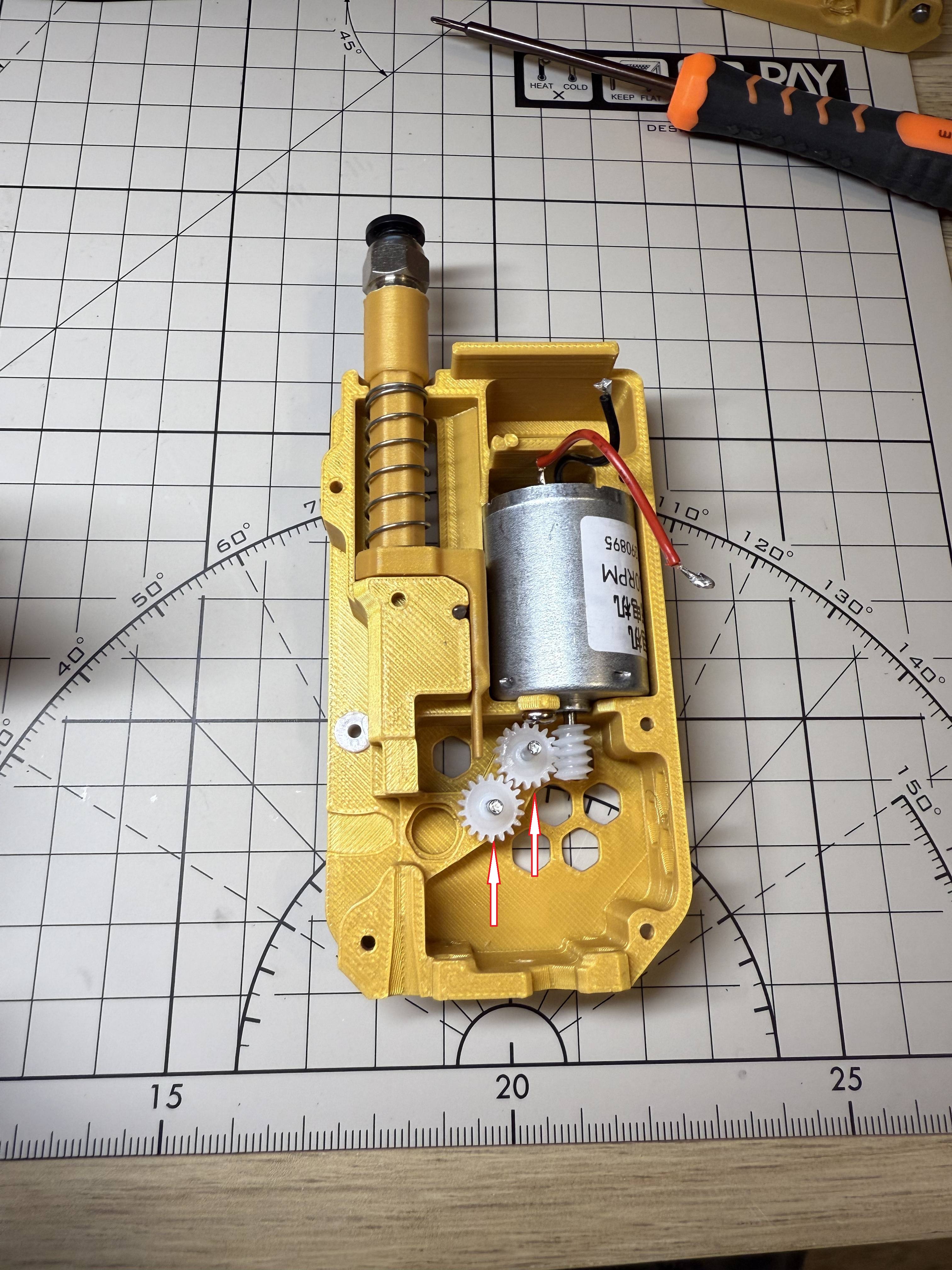
¶ Step 7
Installation of the two gear sets into the frame with the shorter part of the shaft length facing downwards
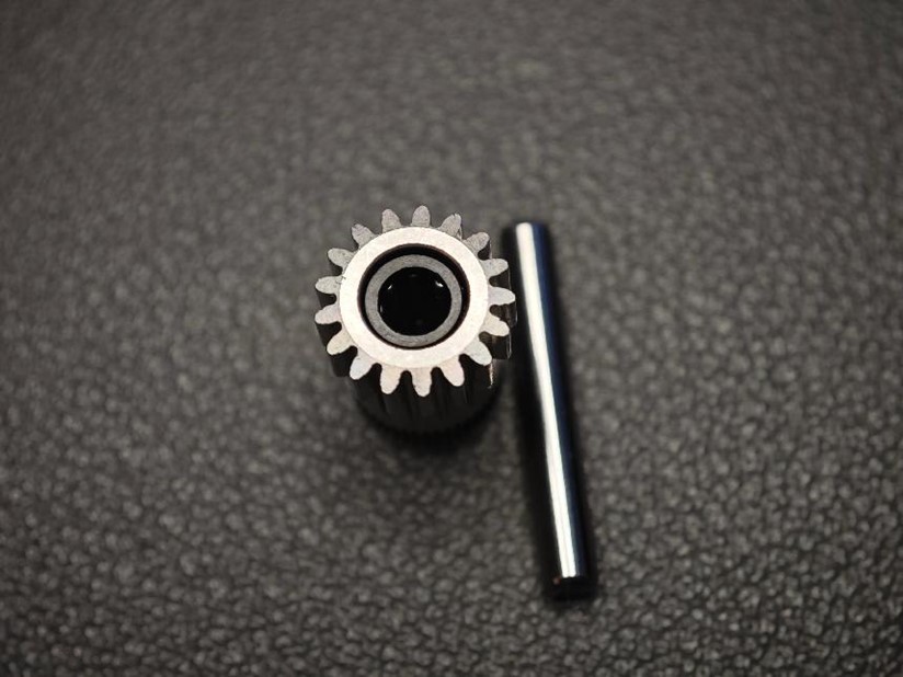
¶ Step 8 - Prapare BMG gear
A word of caution: please handle the combination of BMG gear set, D5*2 shaft and bearings with care, as the fit of the gears and shafts is sometimes very tight, and if it unfortunately gets stuck, it is very difficult to get it out again
Also they are quite expensive.
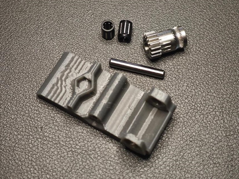
- Gather the following parts:
- Extrusion wheel with screw hole !!!!!! IMPORTANT
- Black set screw
- One thick axle (5 × 22mm)
- Two bearings (MR85ZZ).
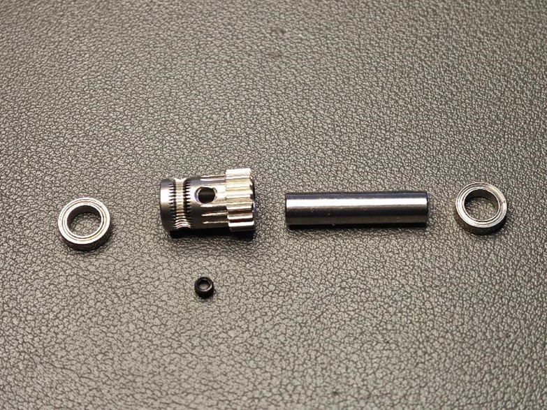
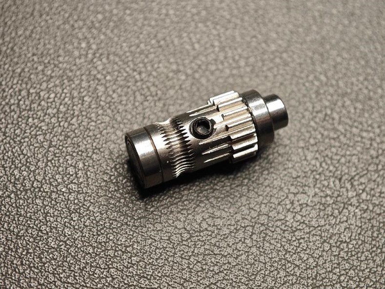
¶ Step 9 Assemble the Extrusion Wheel
- Assemble as shown in the diagram, paying close attention to orientation.
- One end of the thick axle must be flush with the bearing (to allow a flat surface for the magnet).
- Don’t forget to install the black set screw.
¶ Step 10 Place the Extrusion Structure
- Insert the BMG gear into the base housing.
Before close the middle frame, lubricate all gears with grease.
Use a slightly viscous grease, not a liquid lubricant.
¶ Step 11
Install the middle frame, the two gear bushings should match the shafts.
Screw five M2*8 screws on the back.
¶ Step 12
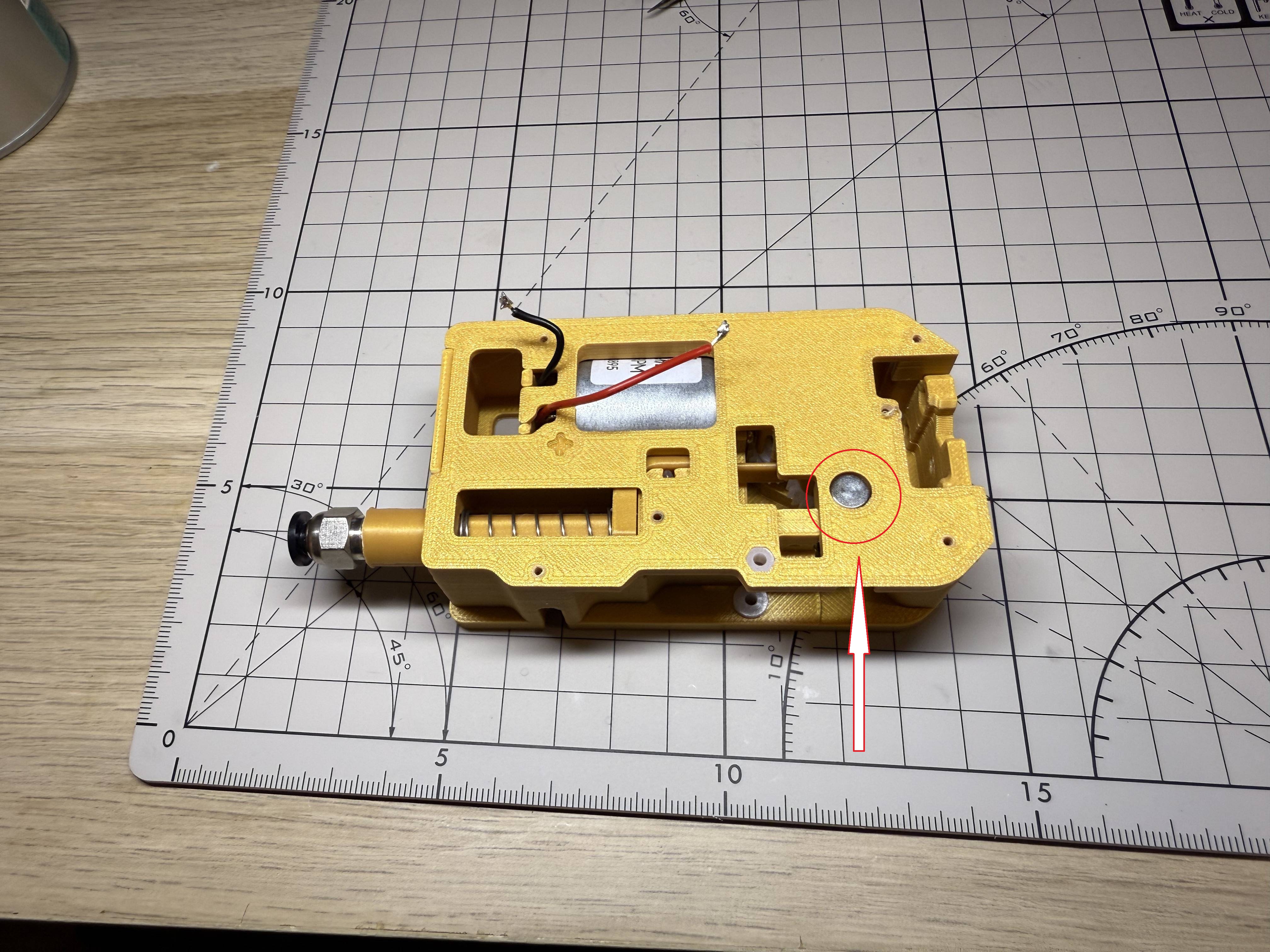
Install the radial magnet into the hole in the centre frame and it should turn smoothly (although at this point you can't turn the gear set because of the 370 motor0)
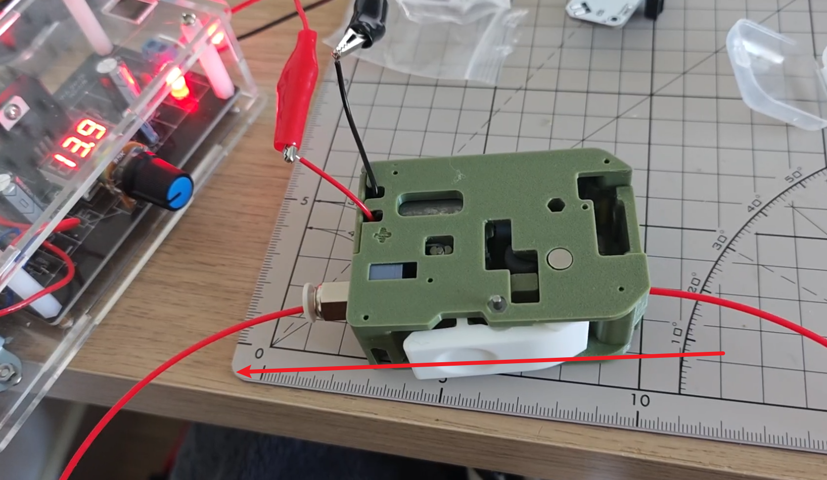
¶ Step 13 Do a test 1
Supply about 9v to the motor and you should see the filament being moved steadily, reverse the supply and you should see the filament moving in the opposite direction.
(I borrow the photo from 130 version, if you connect positive to red wire, filament should move towards right.)
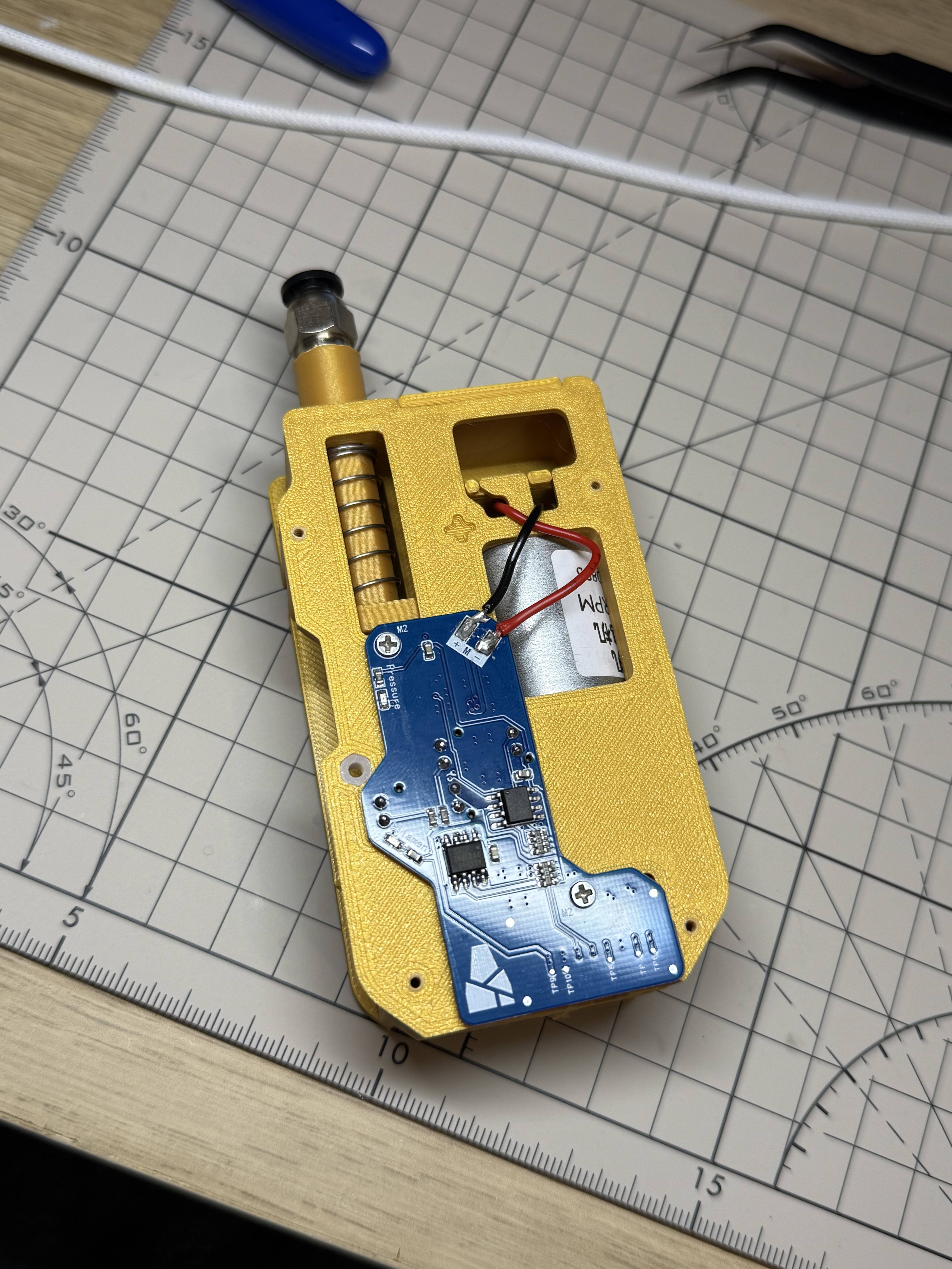
¶ Step 14
Install the sub plate into the centre frame and fix it using two M2*6 screws.
Solder the motor wires to the sub-board. Please note that you should connect the red wire to the negative terminal of the sub-board and the black wire to the positive terminal.
- Motor Positive Terminal -> RED Wire -> Negative of sub-board
- Motor Negative Terminal -> BLACK Wire -> Positive of sub-board
Two 182 gears are used in this model, which will reverse the direction of rotation of the motor, so it is necessary to reverse the power supply
In version 3.14 of the firmware, the author has added the ability for the BMCU to actively detect the direction of rotation of the motor, eliminating the need to actively reverse the wiring to the motor. It is recommended to use this version or newer.
It is known that this function may not be triggered in some cases, and for the time being it is still recommended that the motor be wired according to as indicated on top.
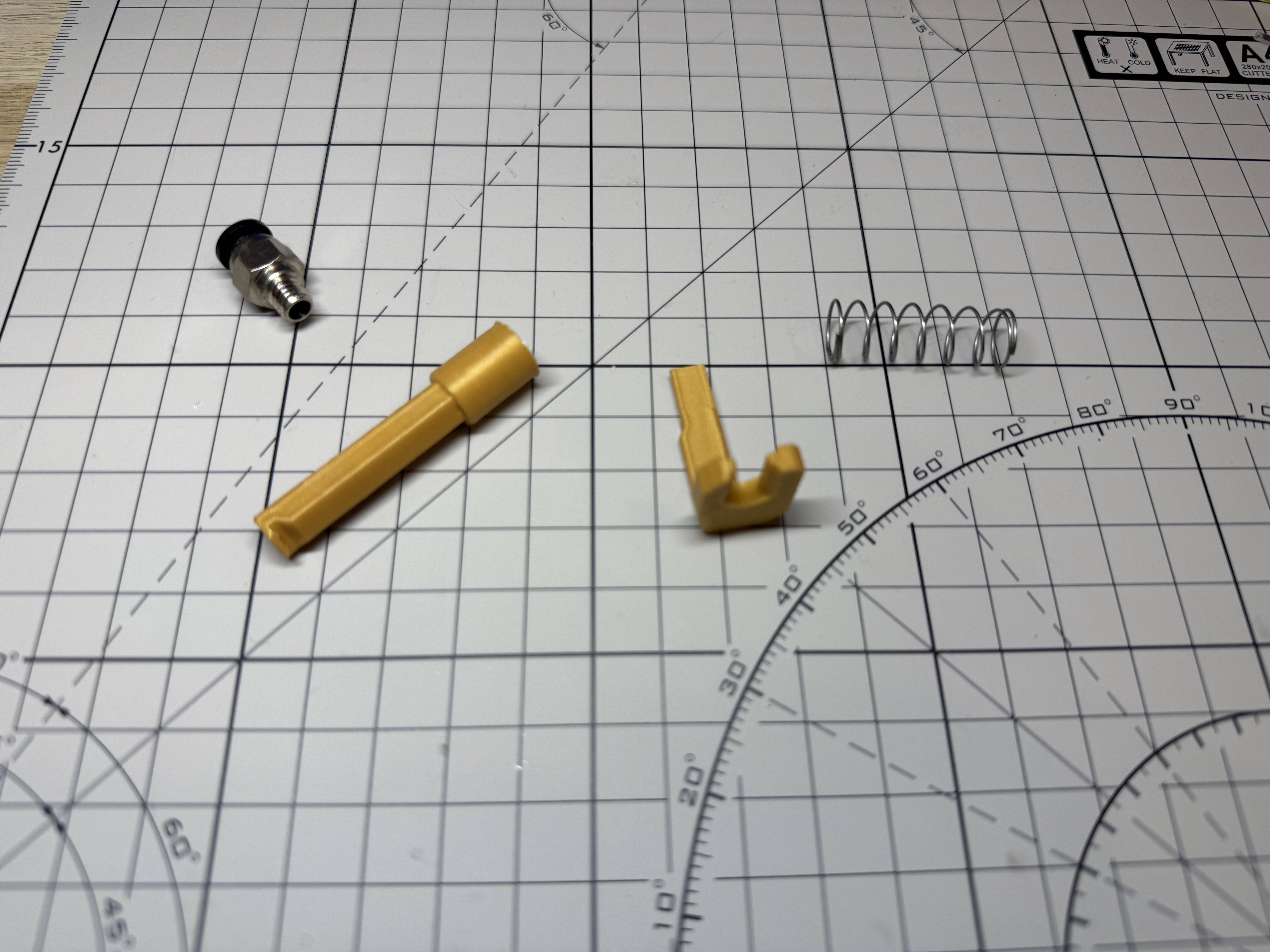
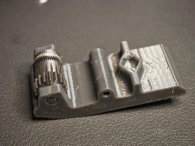
¶ Step 15 Prepare lever Components
You may need to sand or chip the side of this spanner where the support is added, you should make sure that after the shaft is inserted, the BMG gear set rolls very smoothly but does not shift.
- Gather the following parts:
- Two needle roller bearings
- BMG-supplied axle
- Non-perforated extrusion gear
- Printed wrench.
- Assemble as shown in the diagram, ensuring the correct orientation.
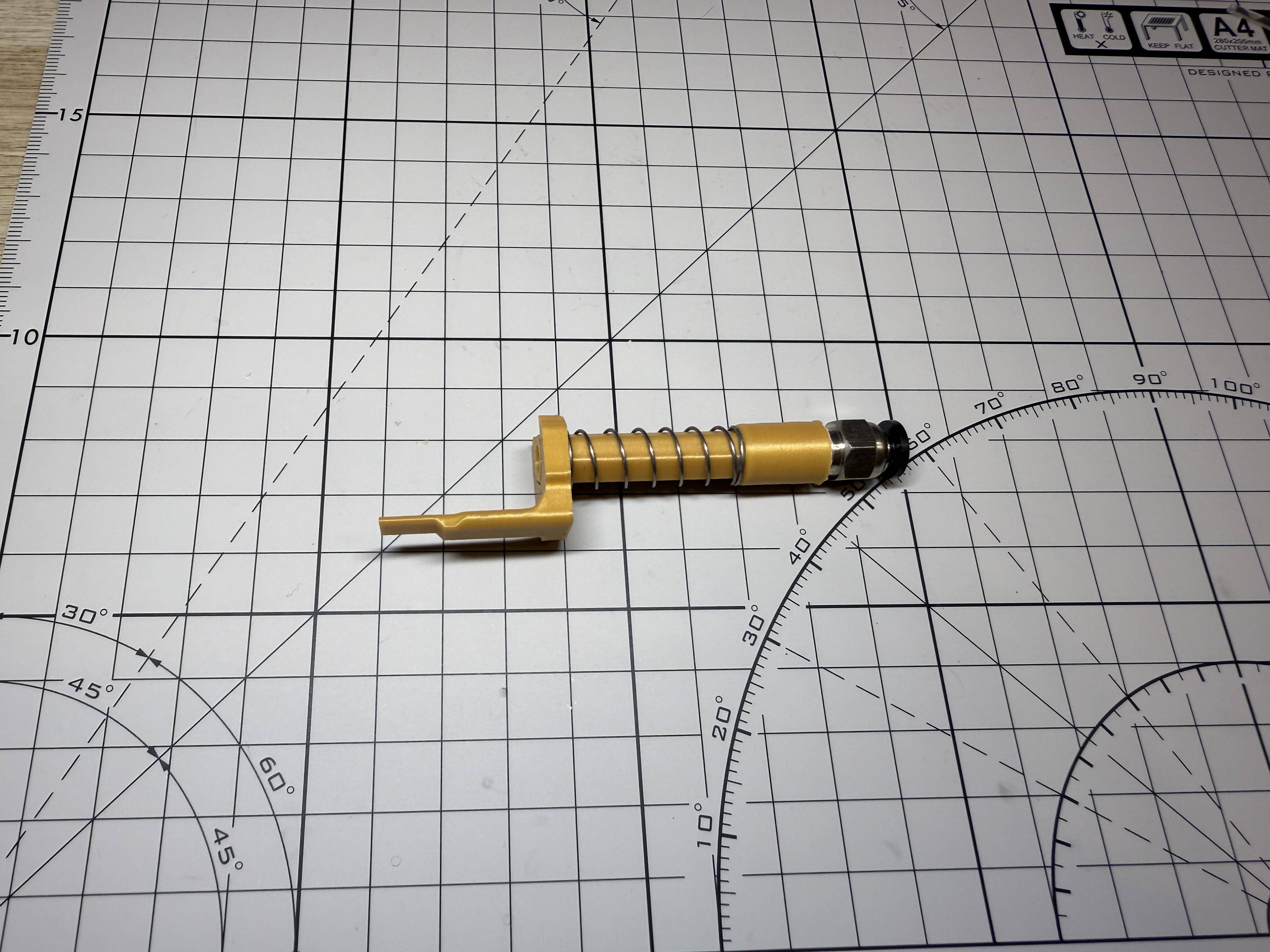
¶ Step 16
Place a small spring, then press the spanner after aligning the empty space of the spanner with the spring
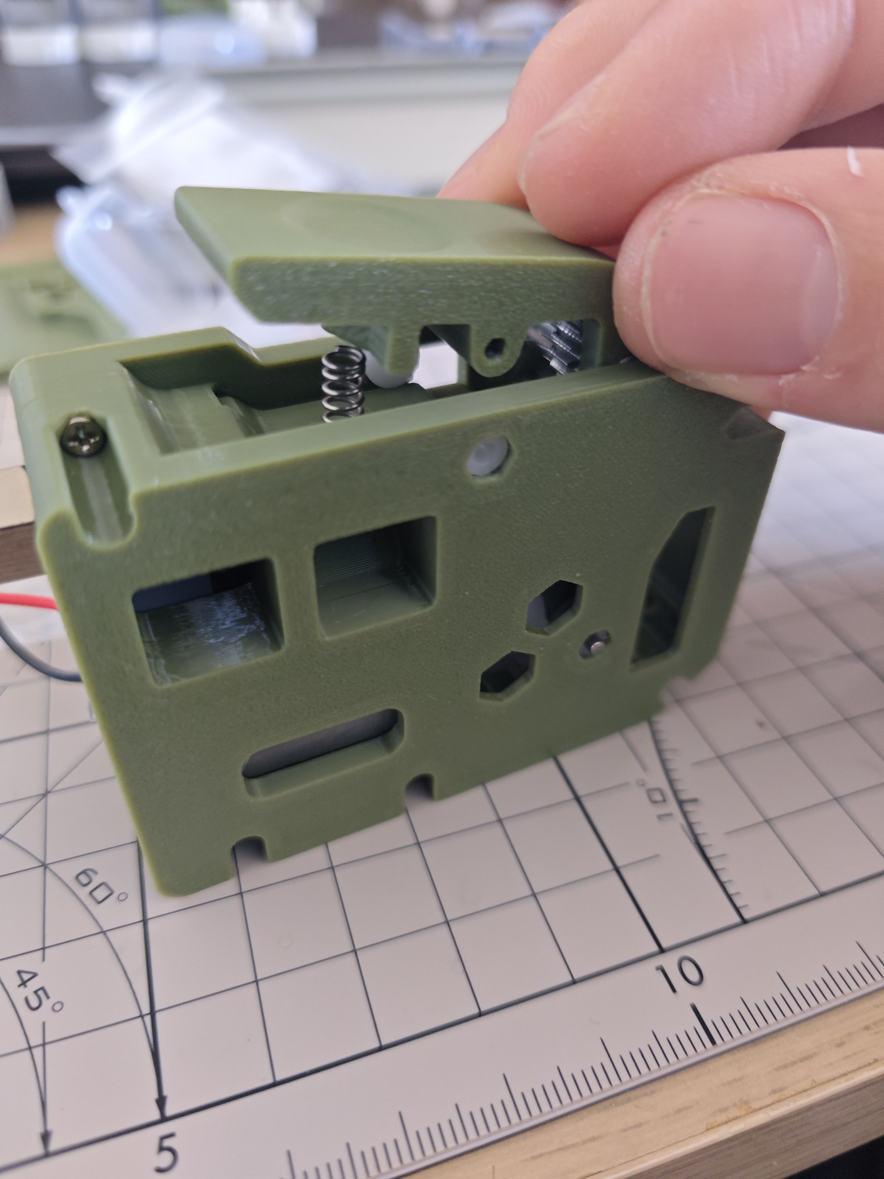
Use two D2*10 shafts, inserted through the sleeve on each side, to secure the lever.
¶ Step 16 Do a test 2
Connect the motherboard with a powerbank or a computer via ttl to usb adapter
and use a 10pin cable to connect the motherboard to the secondary board and you should see that the
Pressure indicatorLED lights upFilament indicatorLED is off
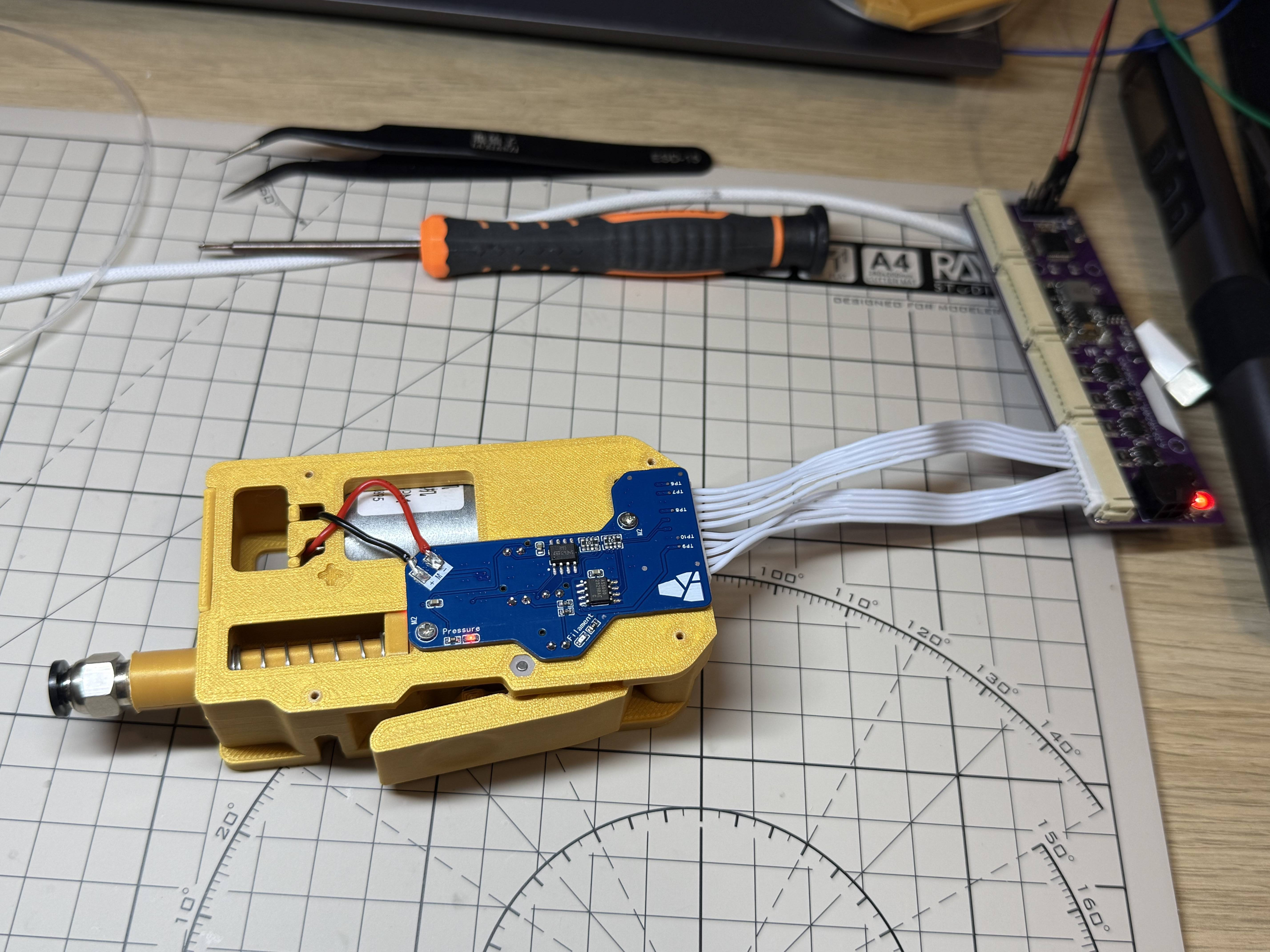
Pull the buffer up and you should see the pressure indicator light go off.

Press the spanner and insert a section of filament, you should see the filament indicator light up.
Move the filament back and forth and the filament indicator should remain lit steadily.

¶ Step 17 Mount to base
Connect the 10pin cable to the sub-board, then
Pass the 10pin cable through the hole in the base and secure the extruder unit from the bottom of the base using a M3*16 screw.

¶ Step 18
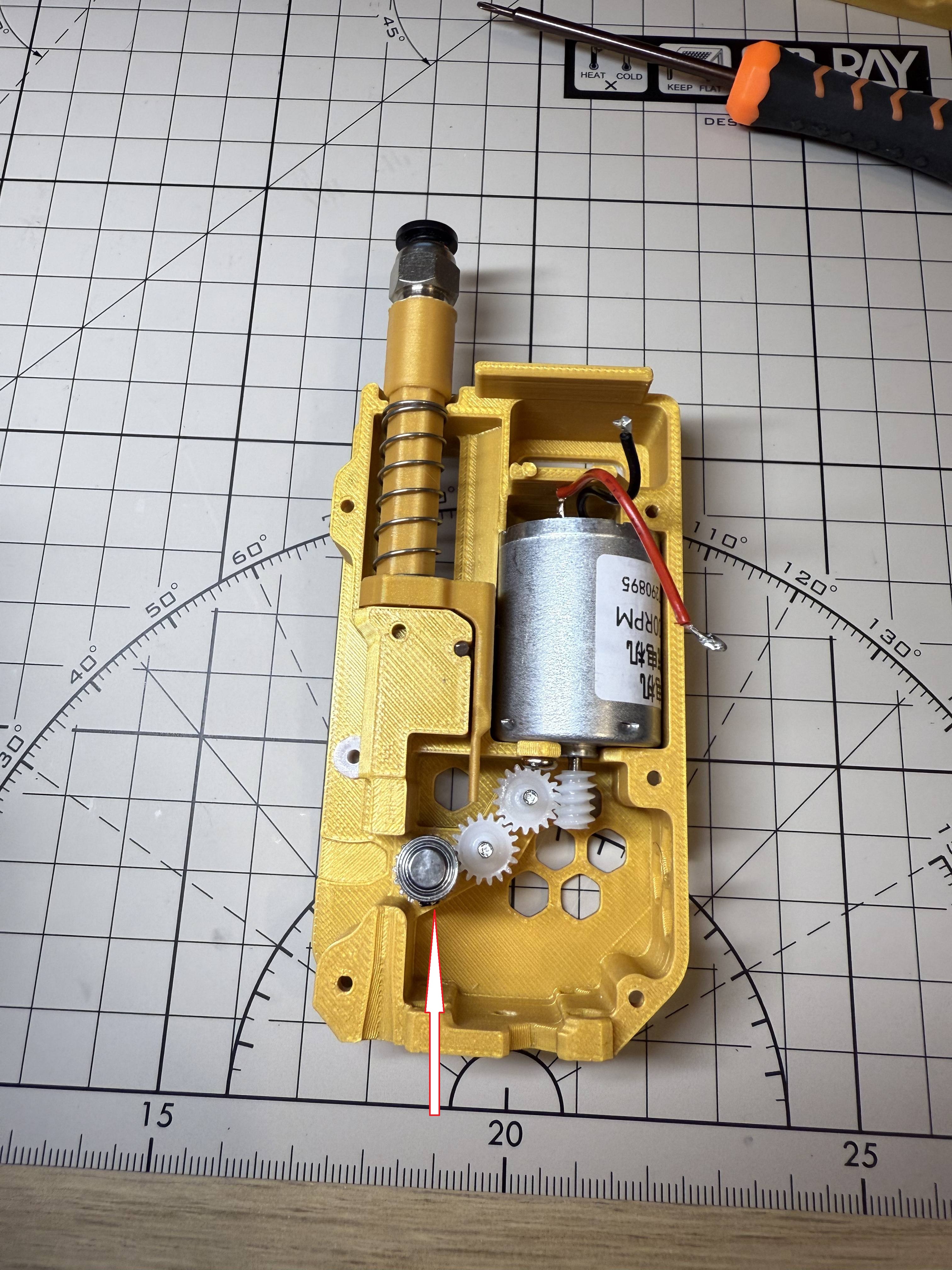
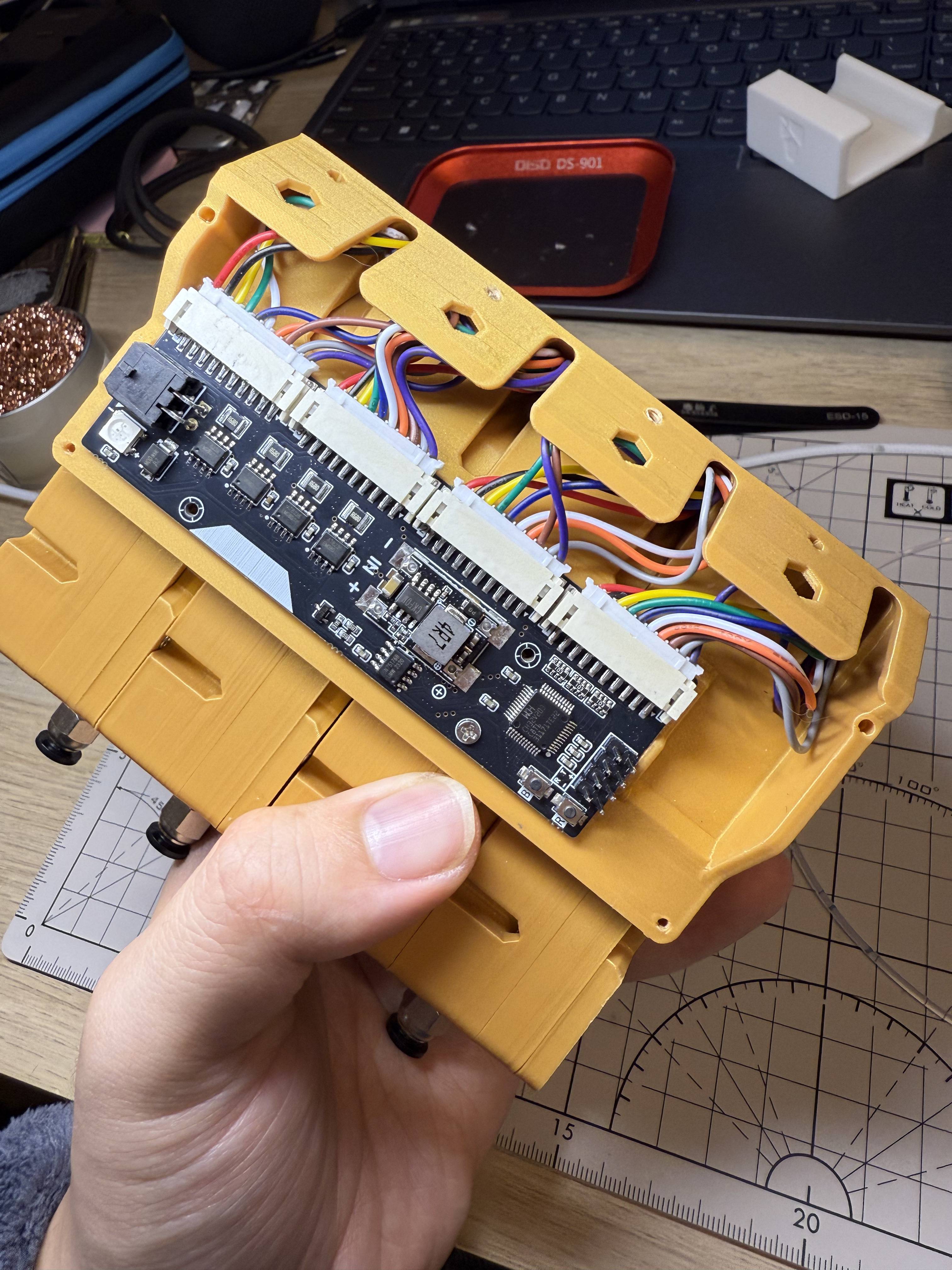
Connect the 10pin cable to the mainboard.
Please be careful, for channel 1, the length of this 10pin cable will be quite tight, please handle with care to avoid breaking the 1st cable in the left for this channel (red in the photo).
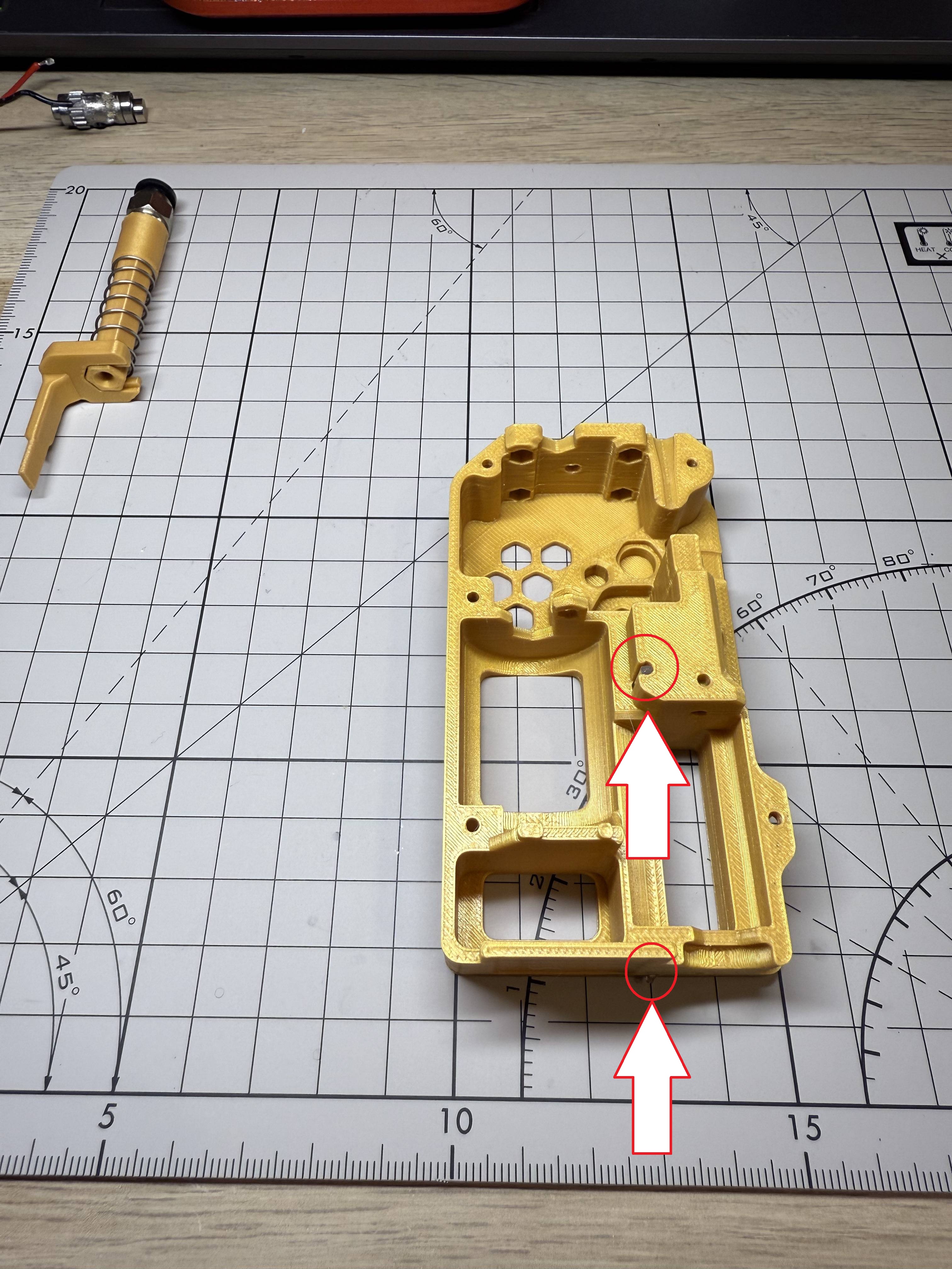
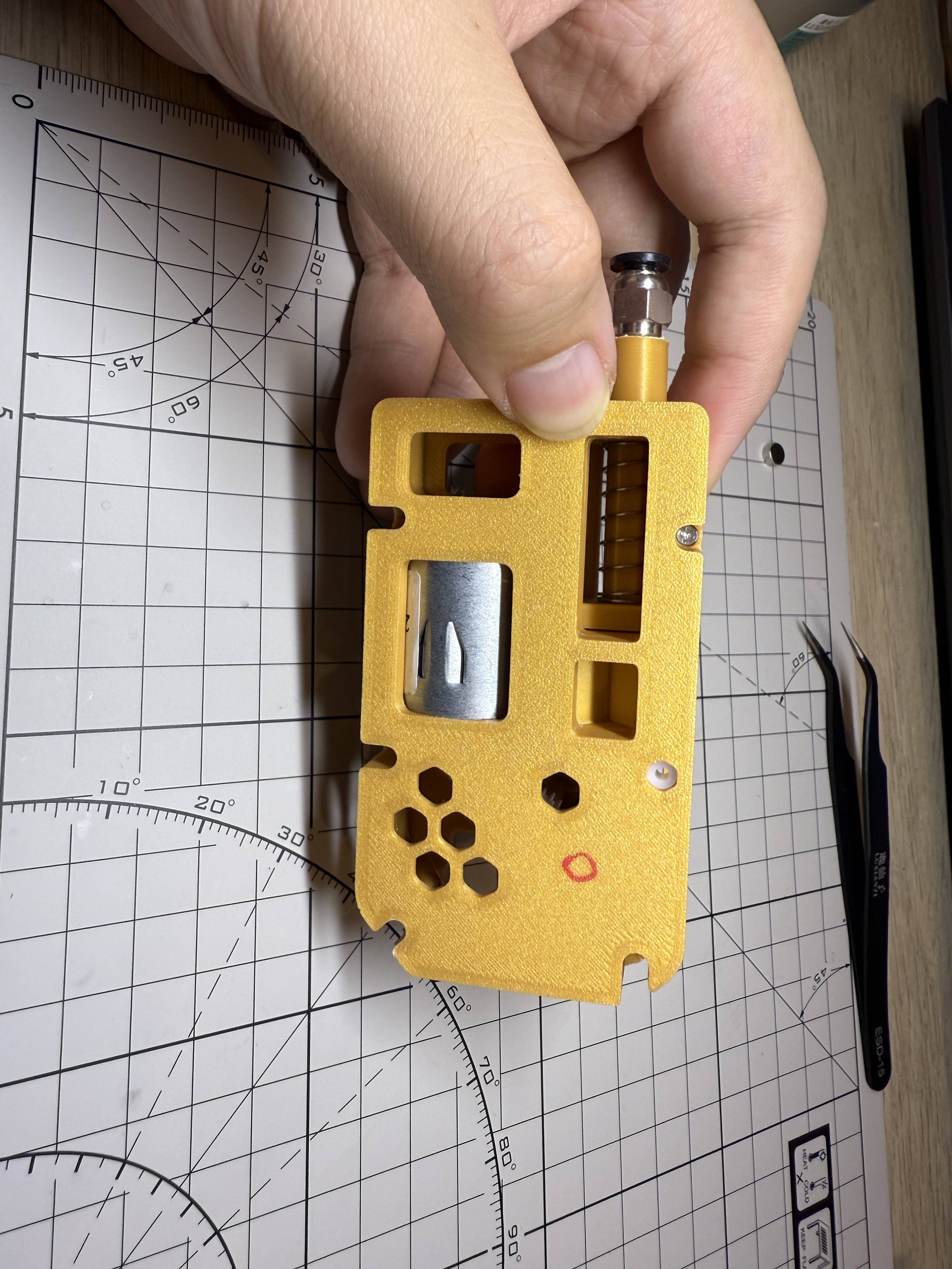
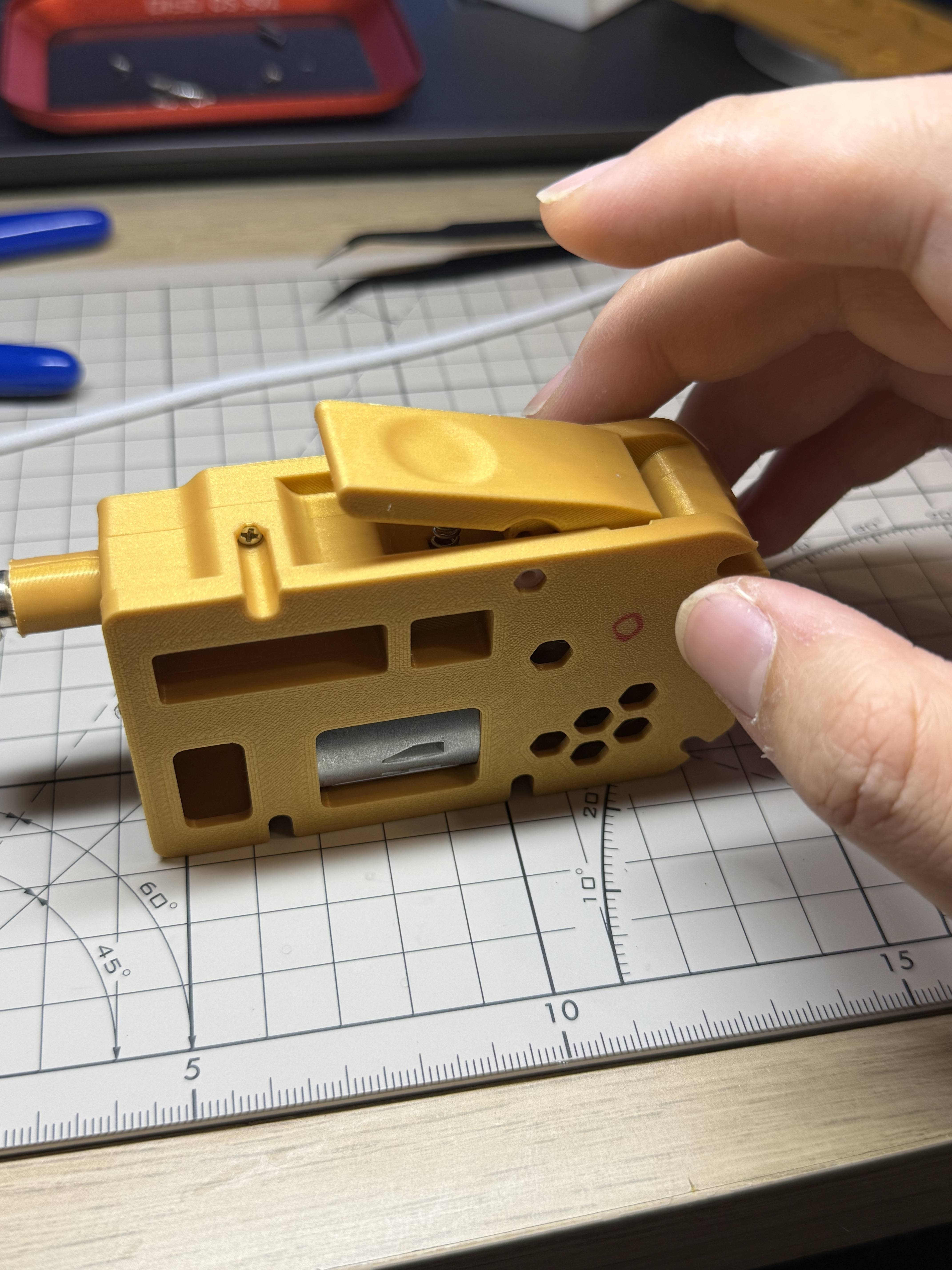
¶ Step 19
You will need to cut a little off the top of the column for the button.
Secure the base cover with m2*8 screws.
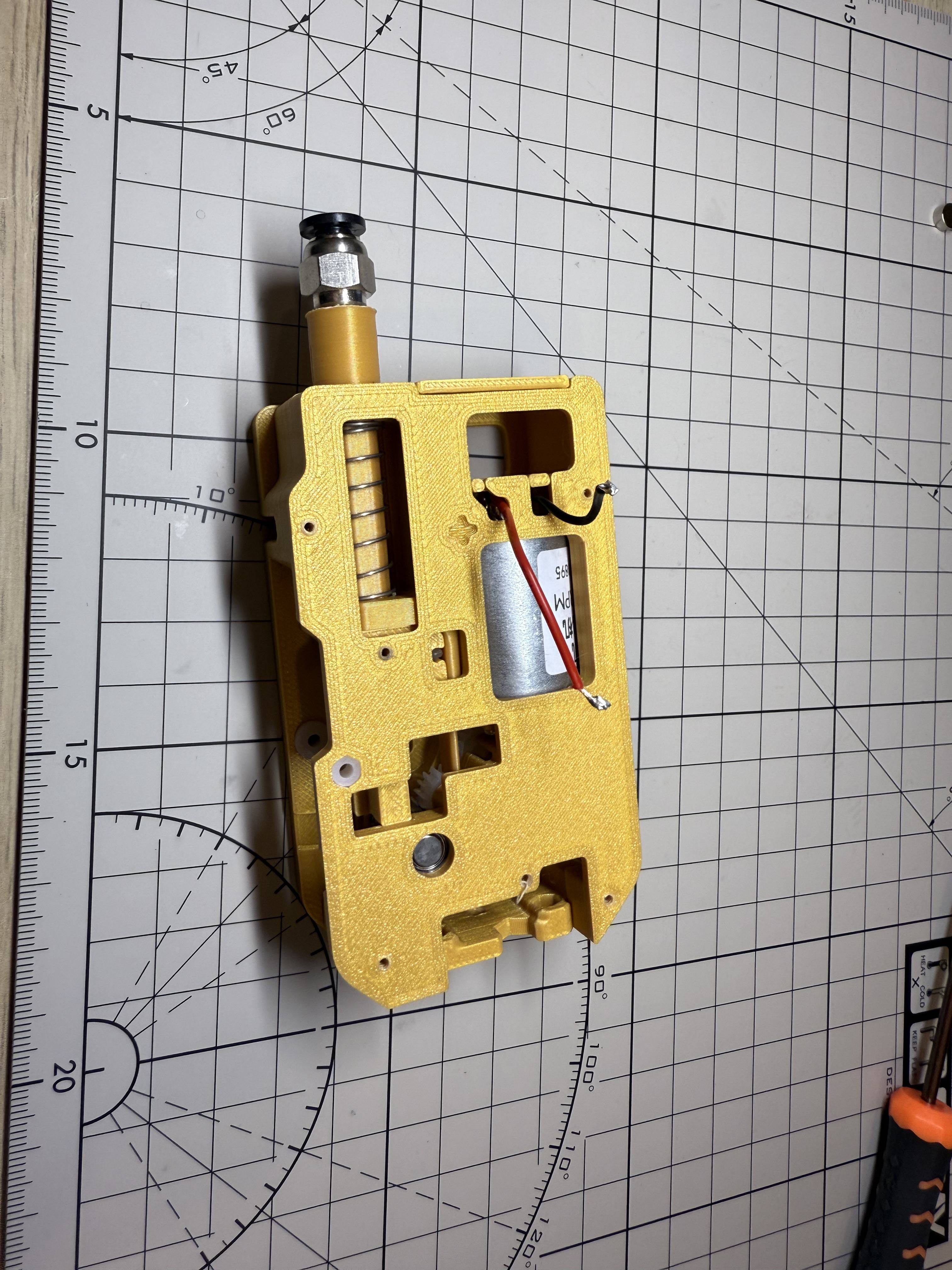
¶ Step 20
Install the bracket with 2 m3*16 screws.