¶ Basic explanation
¶ Definition of To-Ground Value
The to-ground value refers to the voltage drop between a circuit node and ground, primarily influenced by the presence of diodes in the circuit. Due to the inherent characteristics of diodes, their voltage drop typically falls within a predictable range, making the measurement more intuitive and practical for diagnostics.
¶ Why Use To-Ground Value?
In electronic circuits, a large number of diodes exist, and their voltage drop characteristics remain within a defined range. This makes to-ground values an effective and straightforward diagnostic tool.
Although the term is often referred to as "to-ground resistance", it is not an actual resistance measurement. Instead, it represents the voltage drop of a diode relative to ground, measured in volts (V). The reason behind calling it "resistance" remains unclear—possibly a convention within the repair industry. Typically, these values are recorded without units; for instance, a measurement of 0.450V may simply be noted as 450.
¶ Factors Affecting To-Ground Value
Several factors influence the to-ground value, including:
- Chip manufacturing process
- Operating temperature
- Type of diode used
- Output voltage of the multimeter’s test probes
These factors contribute to measurement variations. Therefore, the values provided in reference materials should be regarded as approximations rather than absolute values. The most reliable method to obtain accurate to-ground values is to measure and record them before desoldering a component for comparison with other circuit nodes.
¶ Typical To-Ground Values for Different Components
Highly integrated chips (e.g., CPU): Typically ≥0.2V
Silicon diodes: 0.6V – 0.7V
Silicon transistors: 0.7V – 1.2V
Schottky diodes: 0.2V – 0.4V
¶ How to Measure To-Ground Value
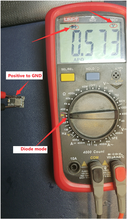
To measure the to-ground value, set the multimeter to diode mode. Many multimeters combine diode mode with the continuity (beep) mode—when the measured value is low, the meter will beep; when it is higher, it will display the voltage drop. Some models require switching to continuity mode and pressing a function key to activate diode testing. When using the meter, pay close attention to the units displayed to ensure accurate readings.
¶ Measurement Procedure
- Set the Multimeter
- Turn the multimeter to diode mode (or continuity mode if required).
- Connect the Probes Correctly
- Place the red probe on the PCB’s GND terminal.
- Use the black probe to touch the test point.
For measuring negative voltage nodes (e.g., -5V, -12V in computer power supplies), reverse the probes (black to GND, red to the test point).
¶ Measure
¶ Exemple
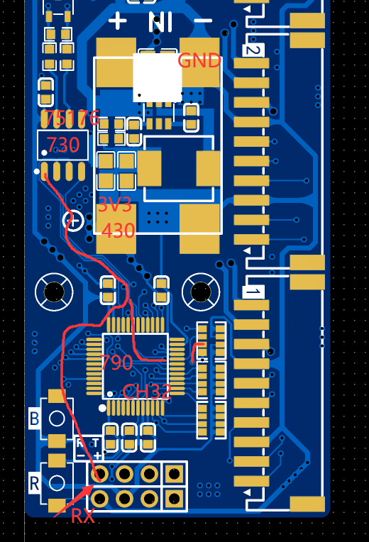
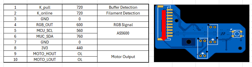
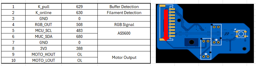
As shown in the diagram, when we place the red probe on any GND point on the PCB (e.g., the negative terminal of the 24V input MX3.0 connector) and the black probe on RX, we may observe one of the following values:
730, 790, 430, 0.000, or OL.
As previously mentioned, the to-ground value represents the voltage drop from the test point through the circuit (via chips or resistors) to GND, and the displayed value corresponds to the component with the smallest voltage drop in the path.
¶ Interpreting the Measured Values
¶ ✅ 730
This value corresponds to the 75176 chip, indicating that:
- The test point is properly connected to 75176, and the chip itself has a normal connection to GND.
- 75176 appears functional, but this does not confirm whether RX is properly connected to CH32 pin 31 or RN3 pin 3.
- To verify, check if these other points have the same to-ground value (730).
¶ ⚠ 790
This value corresponds to the CH32 chip.
Since the minimum expected value (730) is not displayed, this suggests a possible open circuit between RX and 75176.
RN3 should either show the same value (790) or match 75176’s 730Ω reading—if not, further investigation is needed.
¶ ❌ 430
This value corresponds to the 3.3V to-ground value, indicating that RX is shorted to 3.3V.
A possible cause is a solder bridge between RN3 pin 3 and the 3.3V rail.
¶ ❌ 0.000
This means RX is directly shorted to ground (fully conductive to GND).
Further analysis is needed to determine if this is due to a faulty component or an unintended solder bridge.
¶ ❌ OL (Over Limit/Open Circuit)
This indicates that RX is completely disconnected from all connected chips and components.
This suggests an open circuit (e.g., broken trace, lifted pad, or unsoldered pin).
¶ Mainboard
or
¶ Sub-board
or
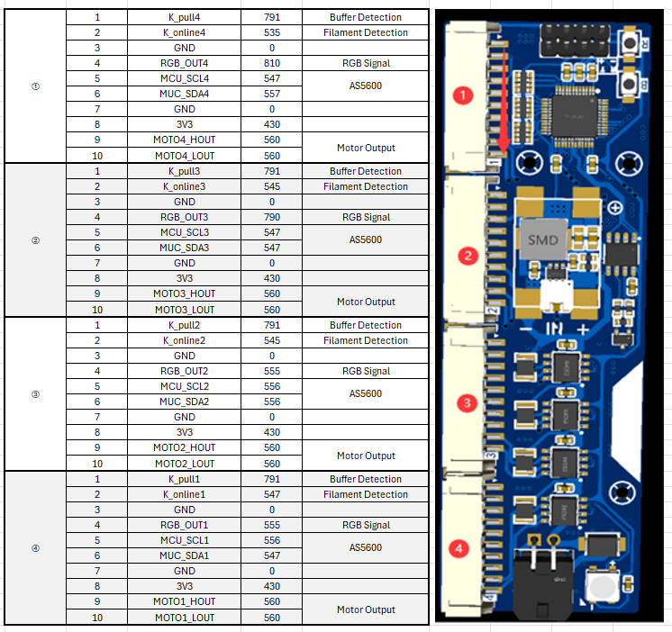
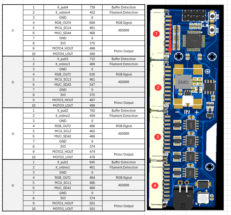
¶ What If My Measured Values Are Different?
If your measured to-ground values differ from the reference values above and cannot be directly compared, don't worry. Just as people have different physical conditions, chips also have variations. Some fluctuation is normal.
Even if the measured value exceeds 1.0V, indicating possible partial breakdown, the chip may still function in some capacity. As long as the point is not shorted to ground, you can safely power it on and test its operation.
¶ What If My Values Match the Reference, but TTL Flashing Still Fails?
If your measured values are identical to the reference values, confirming that wiring is correct and the TTL device is functional, but you still cannot program, unlock, or recognize the chip, try transferring it to a new motherboard:
Only solder the essential components:
- CH32 chip
- RN3 resistor array
- Short the B-button solder pad
Ensure minimal circuit conditions for TTL operation.
Perform programming tests under these conditions before soldering additional components.