¶ PCB - Flashing - Connection
¶ Printer Cannot Recognize AMS, or Main Board Shows Red Light 🚨
Click to expend
After connecting to the printer the motherboard shows a red light meaning that the BMCU and printer communication is NOT established, however power is successfully supplied to the BMCU.If you are not sure about the wire sequence of your cable, check first if the AB wire sequence is wrong.
Then check for possible PCB issues, such as:
- Loose solder joints on components
- Faulty communication wiring (e.g., missing resistors in communication lines)
- Incorrect chip orientation or poor soldering causing virtual connections
Worst case scenario, the AMS connector board or printer motherboard is damaged. Or the 75176 chip on BMCU is damaged.
You should not use the original AMS Lite 4Pin cable from Bambulab because the AMS Lite has the AB signals in the reverse order of the BMCU.
¶ Device Manager Cannot Detect MainBoard or Downloader (USB to TTL)
Click to expend
🛠️ Troubleshooting Steps¶ Verify Downloader Recognition
First, connect the USB-to-TTL downloader alone to your computer (without connecting to the mainboard).
- If it appears as a serial device (e.g., COMx) in Device Manager, the driver is properly installed.
- If no device appears, install the CH340 USB-to-Serial driver (commonly used in many USB-TTL modules).
¶ Check for Short Circuits on the Mainboard
If the downloader is detected when connected alone, but disappears or disconnects when attached to the mainboard, this often indicates a short circuit, typically between 3.3V and GND.
Carefully inspect the circuitry around the CH32V microcontroller for any solder bridges or damaged components.
¶ Ensure Correct Wire Connections
Double-check the DuPont wire order: TX ↔ RX, RX ↔ TX, GND ↔ GND, and 3.3V.
¶ Disable USB Port Protection (if applicable)
On some PCs, aggressive USB port protection or antivirus software may prevent the downloader from being recognized.
Try switching to another USB port or temporarily disabling port protection if you're familiar with your system's settings.
¶ Firmware Update Failed, PC Recognizes Device but Cannot Unlock or Flash Firmware
Click to expend
Solution: https://wiki.yuekai.fr/BMCU/BMCU_Tutorial/BMCU_Flashing#h-5-flash-the-firmware¶ Abnormal Indicator Light Behavior
Click to expend
Check Lighting content on this page : https://wiki.yuekai.fr/en/BMCU/BMCU_testing¶ The motherboard suddenly stops working anymore
Click to expend
We have observed in practice that frequent short circuits or sudden disconnection and damage of the mainboard during operation may be related to the diode located at position D4 on the board. The following insight is provided by @Kongming:The new version of the board introduces a current protection mechanism. When a connection issue or a minor short circuit occurs between the BMCU and the printer, this mechanism protects the printer's interface by redirecting the potential damage to the BMCU board instead. Since the mainboard is relativly cheaper, this tradeoff is generally acceptable.
However, this design also increases the risk of the power module on the new board being damaged by short circuits, which can result in the board suddenly failing—e.g., no lights or printer connection during normal use.
🔧 Recommended Solution:
Remove the diode at position D4 on the new board and short the pads using solder or a piece of copper wire, effectively bypassing the protection feature.
This modification eliminates the current protection but should not raise concern about printer port damage, as such failures are extremely rare.
⚠️ Important Precautions:
Once the diode is removed (i.e., protection disabled), please strictly avoid the following:
- Hot-plugging the BMCU while the printer is powered on — although not every instance leads to failure, hot-plugging always carries a risk of damaging both the BMCU and the printer's motherboard.
- Moving the toolhead when the printer is powered off while the BMCU is connected — this can generate reverse current that may damage the BMCU board.
¶ The motherboard reboot during the prining
Click to expend
Some users have reported that the BMCU may restart unexpectedly during printing. Unlike the previously mentioned cases where the board is permanently damaged, this issue only results in a reboot. However, after restarting, the BMCU does not automatically resume operation—the buffer is no longer triggered, which significantly increases pressure on the filament and may lead to print failure.
This issue is currently suspected to be related to the BMCU firmware, but its occurrence appears to be limited, and the exact cause remains unclear.
No known solution at this time. 😞
¶ Filament movement / Motor / Noise
¶ Motor rotates in the opposite direction
Click to expend
If you are experiencing a motor spinning in the wrong direction, here's the principle behind the issue and how to resolve it:
Since firmware version 3.14, the BMCU is designed to automatically detect the motor rotation direction, which means you no longer need to worry about the polarity of the motor wires during assembly.
However, this direction detection only happens the first time the BMCU connects to the printer after either:
- A firmware flash
- A disconnection and reconnection of the channel
So, if you find that one or more channels are rotating in the wrong direction, here are some solutions:
¶ Solution 1: Re-flash the firmware (recommended)
This is the simplest and most effective method.
- For BMCU-B, flash firmware version 3.14.
- For BMCU-C, flash firmware 0013Plus or a newer version (last update: 29/06/2025).
This will trigger a new round of automatic direction detection when the BMCU reconnects to the printer.
¶ Solution 2: Trigger a redetection without flashing
If you don’t have flashing tools on hand, you can manually force the BMCU to redetect motor direction by disconnecting and reconnecting the problematic channel. Follow these steps carefully:
⚠️ Important: Never hot plugging or hot unplugging.
- Turn off the printer.
- Unscrew the bottom screws of the BMCU base and disconnect the cable of the problematic channel.
- Turn on the printer and wait for 10 seconds.
- Turn off the printer again.
- Reconnect the problematic channel to the BMCU.
- Turn the printer back on.
At this point, the BMCU should reattempt direction detection for the reconnected channel. You can now test if the motor spins correctly.
¶ Solution 3: Manually reverse motor polarity
If the above methods do not work, which can happen in rare cases where direction detection consistently fails or always detects the wrong direction, you can simply manually swap the motor wires (i.e., reverse the positive and negative leads) on the sub-board for the channel.
¶ Filament Inserted, Indicator Light On, but Printer Doesn't Detect It
Click to expend
This may be due to the following reasons:
- First, the magnet signal may be missing, it can be the magnet is forgotten to be installed or the AS5600 chip is faulty. In the absence of the magnet signal, the BMCU will not perform any operation to detect the filament.
- Second, other faults at the welding level, such as the CH32V chip or PH10 socket is not welded properly
Solution:
- Ensure the magnet is installed;
- After installing the magnet, restart the device for detection.
- Check for loose PH2.0 socket connections or broken cables.
¶ No filament Inserted, but System Shows Material Present (Or filament led keeps on) 📏
Click to expand
¶ 🧩 Issue Description
The system reports that filament is present even when no material has been inserted. This can manifest as:
- The filament detection indicator (LED) remaining ON
- In AMS menu display filament always present in a certain channel
¶ 🔍 Cause
This behavior is a known limitation of the BMCU design, which relies on an optical sensor aligned with a narrow structural hole. The sensor detects filament presence when the beam is interrupted.
False positives (i.e., filament always detected) may occur due to:
- Slight height inconsistency of the photoelectric sensor at the factory
- Slight height inconsistency of the photoelectric sensor at the time of soldering
- Shape deviation at the time of printing of the detection aperture
- Debris or dust blocking the optical path
The steel ball version is designed to reduce the chance of this problem, but we have noticed that some users even with the steel ball version still encounter this situation.
¶ ✅ Why It Usually Doesn't Affect Printing
This issue is generally non-critical. A false positive — where filament is always reported as present — is much less disruptive than a false negative, which might prematurely pause a print.
Additionally, the firmware includes a secondary safeguard:
It monitors filament movement within the extruder. If no filament is actually being pushed through, the system will trigger a pause automatically, ensuring job protection.
¶ 🛠️ Optional Improvements
If you'd like to improve sensor reliability, you may consider:
- Gently cleaning the optical hole and slider using a precision tool to remove dust or filament residue
- Slightly enlarging the detection hole with a micro drill bit (1.2 mm recommended)
⚠️ Do not exceed 1.2 mm, or the sensor may incorrectly report "no filament" due to too easy for light passing through - Re-soldering or re-aligning the optical sensor if visibly misaligned
- If you are using non-steel ball version, you can try upgrading -> need reprint almost everything and completely disassemble the BMG gear, and purchase additional parts
⚠️ Impact on Auto Refilling Function
This issue can negatively affect the auto refilling feature. For example:
- Suppose the filament detection on Channel 1 is faulty and always reports filament as present.
- You are about to run out of filament on Channel 1
- You have set up Channel 2 with the exact same material, expecting the printer to automatically refill from it.
However, when the filament on Channel 1 runs out, the printer may fail to recognize the absence correctly. As a result, it might trigger a filament jam error instead of recognizing a normal runout and switching to Channel 2.
If you're using the BMCU mainly for auto refilling purposes, we recommend the following setup:
- Connect the spool that is likely to run out to a channel where filament detection is working correctly in this exemple channel 2.
- Connect the backup spool (with enough material) to the channel affected by this issue in this case channel 1.
This setup will ensure that when the primary spool is depleted, the system can detect it accurately and trigger the refilling process as expected.
🔧 Note: Due to mechanical and manufacturing tolerances, this issue affects many BMCU units to some extent. In most cases, it does not impair normal printing operations.
¶ Material Feeds In and Then Retreats, Unable to Continue Feeding
Click to expend
Solution: This issue is often caused by: - Missing radial magnet - Magnet not rotating with the shaft and bmg gear🛠️ Fixes:
- Use a correctly sized and oriented radial magnet (6×2.5mm)
- Check and ensure the AS5600 encoder chip is properly soldered
- Make sure the magnets rotates sommthly and correctly.
¶ Feeder Motor Spins but Doesn't Feed Material Properly
Click to expend
For BMCU-A:
- Triangular gear may be too tight, preventing engagement.
- Precision errors in external parts may cause jamming.
For BMCU-B/C:
- The worm gear and the 182A gear may be worn, and you will have to replace the worm and gear.
- The worm may not mesh properly with the gear. This is more likely to happen with the BMCU-C. In the early version of the BMCU-C model v0.2, the motor was located too far away from the gear set, making it very likely that the worm did not mesh properly with the gear. In this case, re-seat the motor and manually push it towards the gear while it is being fixed.
¶ Noise during feeding (espcially for BMCU-C)
Click to expend
For all the version:
- Check if screws are pressing against the motor shaft, causing friction.
- Noise during feeding may be due to gear skipping, which is unavoidable.
- Apply lubricant to reduce noise from misaligned gears.
For BMCU-C :
We have observed that the Hall version is more prone to generating unexpected noise during the final stage of the feeding process. This typically manifests as follows:
- After the filament has been successfully inserted into the printer's tool head, the BMCU continues the feeding action for approximately 0.5 seconds, causing noticeably louder gear noise. The noise is from the BMG gear in the lever.
- During this phase, you may also notice that the buffer does not pop up, or does so with difficulty.
Root Cause
The root cause of this issue is insufficient force to allow the buffer to pop up in time, which leads to the printer receiving the buffer arrival signal too late. Contributing factors include:
- Inadequate tension from the lever spring
- PTFE tube being too short, preventing the buffer from fully ejecting
- Excessive bending angle of the PTFE tube, causing increased friction between the buffer and the BMCU housing
- Potential firmware-related issues
Recommended Solutions:
- Replace the lever spring – The originally recommended 0.6×4×10 spring is now considered too weak. We recommend replacing it with a 0.6×4×15 spring for stronger rebound force.
- Reposition the PTFE tube – Ensure the tube is of appropriate length and angle to reduce friction and allow proper buffer movement.
- Update to the latest 0013-Plus-Color-Noise-Heat-Improve firmware – This firmware reduces motor gripping force during the feeding process.
Final Notes:
This issue has been reported by some users, while others have not experienced it. The root causes appear to be multifactorial and may vary between setups. Further improvements to this component may be made in future updates.
¶ Other
¶ AMS Lite Hub / 5-way pop up

Click to expend
The root cause of this problem is that there is a large resistance in the path of the consumable exit, causing the entire PTEF tube to be pulled backwards. This issue occur more offen on BMCU-B, particularly when using older firmware versions. Using updated firmware or firmware versions with extended buffer lengths can significantly reduce the likelihood of encountering this problem.Solution:
- Always check first if there is any particular resistance somewhere in the path of the consumables, e.g. large bending angles or PTFE tubes that are not smooth enough inside.
- It is strongly recommended to upgrade the motherboard firmware to version 3.14 or later, which is more stable and reduces (but does not eliminate) the probability of this issue occurring.
- If the issue persists, building an external buffer may further mitigate the problem. referce makersworld link : Link 1 Link 2 Link 3.
- Additionally, verify whether the AMS Lite hub (five-way connector) is damaged — especially the square-shaped locking clip. If damaged, this module may need to be replaced and reinstalled with the application of interface grease.
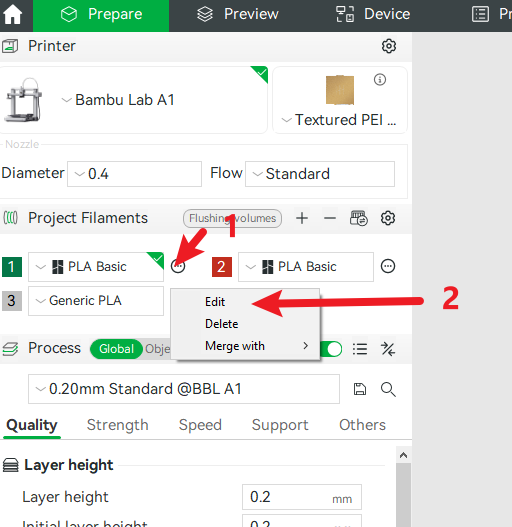
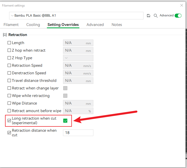
- Disabling retraction during filament cutting may also help reduce the occurrence of this issue.
¶ Single PTFE Tube Being Pulled Out
Click to expend
Some users reported that a single PTFE tube was pulled out, instead of the entire AMS Lite Hub being ejected.
Recommendations:
- Always check for any abnormal resistance when loading/unloading filaments.
- Ensure that the metal clip of the AMS Lite Hub properly secures the PTFE tube.
- One user, David, reported frequent occurrences on a specific filament channel. After disabling the
Long Retraction During Cutoption, he observed significant improvement for that filament channel.
¶ Slicing Software Issues
Click to expend
Some users have reported abnormal behavior after slicing with BMCU, such as:
- All channels being assigned the same color
- Inability to print using AMS
After investigation, this issue was identified as a problem with Bambu Studio itself.
It affects both Windows and Mac versions:
- Mac: Versions prior to
2.0.0.95may encounter this issue. - Windows: Versions prior to
2.03.54may encounter this issue.
Recommendations:
- Upgrade Bambu Studio to
2.0.0.95or higher (Mac) and2.03.54or higher (Windows). - Alternatively, using Oracle Slicer is another effective solution to avoid these problems.
¶ Display errors related to external spool
Click to expend
This error is mostly caused by a slicing error. Please update Bambu Studio.¶ MQTT and authentication errors
Click to expend
It should be noted that this error is not caused by BMCU and does not affect the normal operation of BMCU. This is because BMCU works by simulating an AMS device, rather than communicating via the MQTT protocol.
It is worth noting that Bambu Lab is gradually moving towards a more closed ecosystem. In recent firmware updates, additional security measures have been introduced to restrict the use of third-party software.
Therefore, if you have updated to the latest firmware, it is necessary to also update Bambu Studio and Bambu Handy to eliminate this error message.